Generally, whether one speaks of phase noise or jitter depends upon whether they happen to be a radio frequency or digital systems engineer. Both phenomena are random fluctuations of a time-domain waveform in an oscillator or in a clock. Phase noise is best represented in the frequency domain. It is usually defined as the spectral density of the phase spectrum only, in contrast to the phase spectrum in conjunction with amplitude.
A perfect oscillator, nonexistent in the real world, has a sine-wave output in which all the signal power exists at a single frequency. In actuality, oscillators have noise components that are phase (as well as frequency and amplitude) modulated. This phase noise content takes the form of frequencies that differ from the fundamental.
Phase noise in terms of power is determined by integrating it throughout the available bandwidth, by multiplying the X and Y quantities, which is equivalent to computing the area under the spectral-temporal curve. Phase noise, in degrees, can be converted to jitter, in seconds. Specifically, jitter in seconds is equal to phase noise in degrees divided by 360 times frequency expressed in Hertz.
The same phenomenon, phase noise rebranded as jitter, is the focus of digital systems engineers.
Jitter is applicable to a periodic signal, usually the output of a digital clock or some signal conforming to it. Jitter is an undesirable, often quite harmful effect of deviation from true periodicity. It is an important factor in telecommunications and networking in addition to the many synchronous functions within most digital electronic equipment. Jitter can cause annoying flicker in computer monitors as well as clicks in audio output and garbled data in digital networks.
Like phase noise, jitter can be viewed as spectral density in a spectrum analyzer. It is measured in root-mean-square (RMS) or peak-to-peak values. Jitter frequency and its inverse, jitter interval, are measured in terms of time, length of the interval or cycles per unit of time.
To mitigate jitter, it is necessary first to find its cause, which is often electromagnetic interference or crosstalk. In this diagnosis, these metrics are generally applicable:
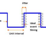
•Absolute jitter is the temporal deviation between actual and ideal timing edge, rising or falling.
•Period or cycle jitter is an observed disparity between a representative period and the ideal period. This is critical in synchronous applications, so the aspiration is to create situations where the shortest and average clock periods coincide insofar as possible.
•Cyclical jitter is the disparity in duration between adjacent clock cycles. If it is excessive, microprocessors won’t work, setting the stage for electronic equipment and network failure.
Jitter can be random or deterministic. Because it is caused by thermal noise that originates in all electronic components including low-impedance conductors, random jitter conforms to a Gaussian curve. The other type of jitter is bounded. Consequently, it is easily recognized in a properly-scaled time domain display. Examples are duty cycle distortion and intersymbol interference, where at worst successive symbols combine to make an unintelligible mix.
A major cause of jitter as it appears at an ADC is a noisy clock. As data rates have risen, clock lock quality has had to keep up with demands. Engineers are tasked with evaluating system performance by looking at clock noise in the context of bit error rate.
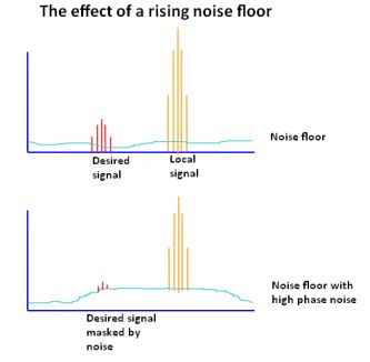
and eventually feeds to the antenna together with the wanted signal. So the wanted signal is
surrounded by a band of noise originating from the phase noise of the LO. The noise generated can spread over several kilohertz, masking nearby lower
power stations.
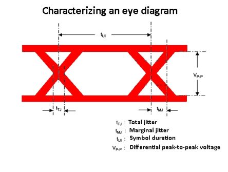
The purpose of quantizing jitter is to mitigate it and limit the bit error ratio. Voltage noise ultimately results in bit errors because the signal voltage moves vertically across the logic thresholds. Jitter, in contrast, causes bit errors because signal transition timings move horizontally across the sampling point, which is the voltage and time location where an ADC decides whether a bit is logic high or logic low.
Clocks vary widely in quality. The usual clock specifications are peak-to-peak phase jitter, period jitter, and cycle-to-cycle jitter. We can look at these parameters, but a complete evaluation involves knowing the clock in its entirety, in addition to the requirements of the ADC, not to mention the ultimate application. The clock data sheet includes the above values but also provides additional specifications, such as RMS of whole jitter distribution, RMS random phase jitter at various bandwidths and phase noise at the carrier for various offset frequencies. ADC aperture pertains to the jitter rate that can be tolerated.
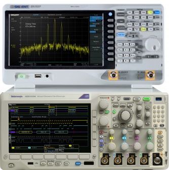
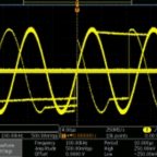
To determine the time interval error range, the most basic instrument is a real-time digital storage oscilloscope. For a reliable interpretation, the oscilloscope bandwidth should be three times the data rate. More sophisticated measurements, if needed, are best performed by a phase noise analyzer. Lacking this expensive and highly specialized instrument, many analysts make use of a spectrum analyzer.
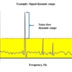
The easiest way to display and measure noise in a spectrum analyzer is to configure instrument settings so that a single sideband is shown on the screen. Phase noise manifests as energy outside of the fundamental, above and below it in frequency.
Because phase noise degrades data transmission performance and causes adjacent channel interference due to its spectral range, bit error rate and spurious emissions need to be measured and mitigated. The spectrum analyzer is capable of displaying the deviations from the ideal because the center, start, and stop frequencies and span can be easily set.
For a valid measurement, the instrument’s sweep rate must be sufficiently high in comparison to the phase noise level of drift. In actual practice, phase noise levels are keyed to a stable reference so as to maintain a reasonable drift. This is opposed to a free-running oscillator, which exhibits greater drift and less stability.
To begin a phase noise measurement using a spectrum analyzer, connect it to the unit being tested with inserted attenuation to avoid overloading the instrument. Widen the span if necessary until the carrier intersects with the instrument’s noise floor. You need also to consider the bandwidth of the spectrum analyzer’s internal filter. A wide-frequency filter reduces the time required to traverse the span.
Technique is all important. Lacking a full-scale faraday cage, screened leads and separation from noise sources will limit RF interference. A harmful source of noise is the power supply. Switching power supplies generate significant noise because of their high-amplitude voltage spikes.
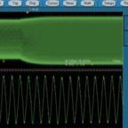
The real-time spectrum analyzer has been optimized to show how frequency, amplitude and modulation characteristics evolve over short time intervals. To see the dynamics of an RF signal, the real-time model is preferable to swept spectrum and vector signal analyzers. Due to its expense, typically greater than that of a comparable digital oscilloscope, the real-time spectrum analyzer has been out of reach for many users. The PC-based spectrum analyzer, taking advantage of the computing power and display characteristics of a user supplied PC, is a cost-effective alternative.

Leave a Reply
You must be logged in to post a comment.