Any treatment of wave polarization must begin with a discussion of the differences between transverse and longitudinal waves. That is because polarization either as a process or a state applies only to transverse waves, not to longitudinal waves.
Longitudinal waves are those in which the oscillations are in the direction of propagation. Examples of longitudinal waves are sound waves in a gas or liquid such as human speech conveyed through air or cries of underwater whales in the ocean. Because the physical motion of the oscillating particles is in the direction of wave propagation, this energy cannot exhibit polarization.
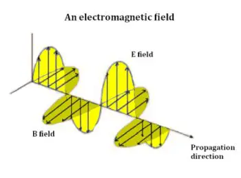
field vector B oscillates in a direction perpendicular to that of the electric field vector and to the direction of propagation of the wave.
In contrast, electromagnetic radiation is made up of transverse waves. The oscillating motion is perpendicular to the direction of propagation, so this energy may exhibit polarization. An example of energy having transverse waves is light, which, as James Clerk Maxwell demonstrated in A Dynamical Theory of the Electromagnetic Field (1865), is a form of electromagnetic radiation.
Light polarization may be linear or elliptical (of which circular polarization is a limiting case). In elliptical polarization, the fields rotate at a constant rate. Depending upon the direction of rotation, it may be right or left polarization as viewed from the source.
Electromagnetic radiation is usually unpolarized or it may be said to exhibit random polarization when it comes from a lamp filament, fire, sun or most other natural or human-made sources. Most electromagnetic radiation is called “incoherent”, meaning that it consists of random waves that have varying frequencies, phases and polarizations.
There are various ways to polarize light, the simplest being to pass it through a polarizing filter. A wire-grid polarizer consists of fine metal wires in a plane. Light waves pass between the wires, but not through them. The separation of the wires must be less than the wavelength of the light to be affected, and the wires themselves must be still smaller. (Today, polarizing filters are made by far cheaper, chemical means.) If you want to see an intersecting wire grid polarizer that blocks all radiation of a given wavelength, look at the glass door of your microwave oven. The longer microwave radiation is blocked while light passes through.
Modern polarizing filters are widely used, in everything from camera filters to inexpensive polarizing sunglasses. As an interesting experiment, remove the lenses from polarizing sunglasses that are being discarded. If you look through both lenses separated by a small air gap, you will see that the amount of light transmitted can be varied by rotating one lens 90° with respect to the other.
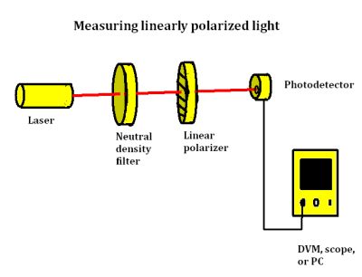 Test gear can be set up to check the polarization state of a laser and define its polarization direction. The idea is to measure the transmission of laser light through a linear polarizer as its transmission axis is rotated. The intensity of the transmitted light can be measured by a light detector connected to a voltmeter, scope, or PC. The resulting reading is proportional to the intensity of the light that hits the detector. Knowing what’s called the transmission function, it is possible to deduce whether the laser light is completely linearly polarized or partially polarized.
To understand the transmission function, consider a source of linearly polarized light with the electric field vector Eo oscillating along the direction of polarization. Assume Eo oscillates along the x-axis, that of the polarization direction of the light. Suppose a polarizer sits in front of the light source, with its transmission axis making an angle α with the polarization direction of the incident light. Only the component of the electric field vector that is along the transmission axis can pass through the polarizer.
Consider the projection of Eo along the transmission axis. As light passes through the polarizer, the amplitude of the electric field vector is given by E = Eo cos α. The intensity I of the light can be shown to be proportional to |E|2. So the intensity of the light after it passes through the polarizer is proportional to Eo2 cos2 α. Equivalently, the transmitted intensity I is related to the incident intensity Io by I = Io cos2 α. This equation is called the transmission function of the linear polarizer.
From this equation, if α = 90 (or 270) degrees, then I = 0. So if the polarizer rotates such that no light can pass through, the polarizer’s transmission axis must be perpendicular to the polarization of the incident light. But if the transmission axis is aligned with the polarization direction, α = 0 (or 180) degrees and the transmission is maximum (I = Io).
This analysis assumes a totally linearly polarized light source. In general, the transmission
function is I = A cos2 α + B where A and B are constants. For light which is completely linearly polarized, B = 0. If unpolarized or partially polarized light is used, B will not be zero.
For non-zero B, rotating the polarizer cannot completely extinguish the light.

To measure laser light polarization, we turn on the photodiode. To avoid saturating the photodiode with too much laser light, most setups include a neutral density filter. Both the neutral density filter(s) and the polarizer are oriented so the laser beam is perpendicular to all the optical surfaces and passes through the centers of all the optical devices. It is also important to block unnecessary reflections. We then turn the photodiode on and record the voltmeter readings as the polarizer rotates by increments, say every 30°. We also record the voltmeter reading while blocking the laser beam. This is the background signal that must be subtracted from the data.
Of course, quantum mechanics states that light also exists as elementary particles known as photons. How can this be consistent with polarization, which would seem to require waves?
The corresponding attribute in photons is spin, which really has nothing to do with rotation. As currently understood, a photon has either left-hand or right-hand spin based on its propagation vector. Circularly polarized photons exhibit only left- or right-hand spin. Linearly polarized waves have equal numbers of photons with left- and right-hand spin.
We have noted that sound waves traveling through a liquid or gas medium are longitudinal, where polarization does not take place. But occasionally sound waves are conveyed by a solid medium, such as birefringent crystals. In this situation, the electric or magnetic field may have both transverse and longitudinal components. Moreover, in isotropic media such as some metals, the electric and magnetic fields are neither purely transverse nor purely longitudinal. They are known as hybrid modes.
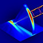
Birefringent crystals are those such as quartz that exhibit double refraction or birefringence and have two indices of refraction (along directions of crystalline symmetry): an ordinary index and an extraordinary index. The speed of light through them is different in different directions. Normally, as light enters such a material, it splits into two components: an ordinary ray along an ordinary axis and an extraordinary ray along an extraordinary axis. These two components travel at different speeds along different directions, which results in a phase difference between them. However, if light falls on the crystal such that the plane of incidence is parallel to a characteristic direction called the optic axis, both rays travel in the same direction and with the same speed.
There is no appreciable attenuation or change of the waveform’s amplitude when light passes through the birefrengent medium. What does take place is a differential phase delay, which we see as differential bending of the light in two distinct amounts. The phenomenon is used to good effect by investigators who wish to visualize stress in transparent materials. Variations in stress in transparent media affect refraction of polarized light to different degrees so that areas of stress appear as different colored areas. Wearing polarizing sunglasses, we sometimes see this phenomenon as vivid spectral displays that appear embedded in automotive glass.
Dichroic media are those in which one polarization mode is attenuated. This can arise when there is linear or circular polarization. If the amplitude is substantially reduced in one mode, the medium is considered a polarizing filter. In this instance, the output with respect to power at the input is 50%. When two such filters sit in series so light passes through both, the combination can be made opaque by rotating one of them a quarter turn with respect to the other.
Polarization also happens in varying amounts at the junction of two materials each having a different refractive index. This effect is described by the Fresnel equations, developed by Augustin-Jean Fresnel (1788-1827). These equations also pertain to the reflection of light, which was known to have polarizing effects.
Light traveling through two media of differing refractive indices gives rise to both reflection and refraction. The Fresnel equations quantify the amount of light that reflects and refracts, as well as the phase shift of the reflected light.
Radio transmission and reception antennas, including the microwave variety, comprise an enormously complex subject, but some simple observations regarding polarization are possible. Most antennas a linearly polarized. Some have elliptical polarization. Radio engineers must pay close attention to antenna polarization. Transmitting and receiving antennas require the same polarization, vertical or horizontal. Otherwise reception will be at best partial. Radio uses vertical polarization while TV uses horizontal polarization.


The top graphic shows a left-handed transverse wave. Oops.
Does it matter whether I use a light sensor rather than a photo detector?