Reflections typically arise when a beam of light strikes a polished flat reflective body whose surface is perpendicular to the beam of light. Then the transmitted light minus loss in two-way transit appears at the source. This is similar but not exactly equivalent to an electrical signal traveling through a conductive medium that has an impedance mismatch or discontinuity along the way. The signal returns to the transmitter/generator, but it is by no means reflected, even if the original signal is light, propagated through an optical fiber.
Assuming that we are dealing with an ac electrical signal, the “reflected” signal returns to the transmitter, “colliding” with outgoing transmitted data. Despite the misleading terminology, the harmful effects are real and include garbled transmissions, data loss, poor frequency response, excessive power at the transmitter, and high voltage in a power line.
For lack of a better term, we’ll stay with existing terminology. Reflections in a transmission line evolve into standing waves that are established and persist as long as the conditions that caused them to continue unabated. Electrical energy, moving through a two-wire transmission line such as coaxial or category cable, encounters an open circuit, short circuit, other impedance mismatch or line discontinuity.
When the signal reaches the point of an open circuit, the current will be zero. However, due to conservation laws, the energy will not cease to exist. Because it has to go somewhere, it will flow back toward the source, encountering whatever wave energy that may be proceeding downstream. These waveforms are additive, resulting in high-amplitude peaks that are quickly seen at the transmitter.
The situation is essentially the same if there is a short circuit at the end of the line, except that voltage is substituted for current. (Current cannot flow through an open circuit. Voltage cannot appear across a short circuit.) In the short circuit situation, charge continues to arrive, and conservation of electric charge results in an equal but opposite current appearing to enter the line. This produces the phenomenon but it would be inaccurate to call it a reflection.
In the short-circuited line, rather than current it is a voltage that travels back toward the transmitter. If the line is properly terminated in its own characteristic impedance, electrically it appears as an infinitely long line and continues to absorb the signal with no reverse current, voltage or data collision. An impedance mismatch or discontinuity at some point along the line results in part of the signal being returned to the transmitter and part conveyed to the receiver.
As in any troubleshooting, diagnosing poor performance in a transmission line is a matter of observation and logic. If this is a new installation that has never worked, make sure the correct cable was installed. Visually inspect the cable for any kinks or damage. Securing hardware should be tight enough to hold the cable in place without deforming it. Check terminations at both ends. They should be snug but not overly tight. If the cable is not too long and the entire length is accessible, it may be worthwhile to replace it with a new segment of the correct characteristic impedance.
Characteristic impedance cannot be checked with an ohmmeter, with or without the ends shunted. It can be calculated by means of a complex formula involving cable parameters, but this is rarely done in the field. Transmission cable is manufactured to precise tolerances and the characteristic impedance is marked on the jacket. This metric is independent of length because the greater series impedance of a longer segment is balanced by the greater parallel capacitance.

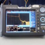
The presence and location of any discontinuity in transmission cable, whether installed between transmitter and receiver in the field or stored on a reel in the warehouse, can be determined by a wonderful instrument known as a time domain reflectometer (TDR). There are variations, but typically the cable under investigation is disconnected from the transmitter and, after checking with a multimeter to assure that there is no unexplained voltage in the cable, it is connected to the TDR input/output.
A pulse generated by the instrument, usually a half-cycle sine wave, is applied to the transmission line. The TDR has a small flat screen with X and Y axes. It displays the sent pulse along with any reflections. The absence of any reflection indicates that the medium has no discontinuities or impedance mismatches and that it is properly terminated at the receiver. (Even a good medium, however, may exhibit faint reflections.)
The reflected waveform looks like the pulse that is sent out by the TDR, except for sign and magnitude. The magnitude of the reflected pulse as shown in the display depends on the amount of impedance change, and of course, loss in the conductor is also a factor. If there is a steep rise in the impedance, the reflected signal will have the same sign as the applied pulse. If there is a steep decrease, the reflected signal will appear as a mirror image below the X-axis.
The reflections are displayed as functions of time. Taking into account the propagation rate of the medium, it is possible to determine precisely the location of any discontinuity. For a long, buried cable, this greatly simplifies repair.
An optical time-domain reflectometer (OTDR) is similar, but rather than applying an electrical pulse at the upstream end of a conductive metal cable, it sends a light pulse into an optical fiber and analyzes the reflection. The OTDR is available as a full-featured bench model, battery-powered, hand-held model, or as the much less expensive fiber break locator.
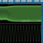
Getting back to the electronic TDR, if you don’t have one and can’t currently justify the purchase, there are some less expensive alternatives, assuming you have an oscilloscope. Some oscilloscope models have compatible application modules, which can be obtained from the manufacturer and installed in the instrument for TDR measurements. An example is the Tektronix 80E04 TDR sampling module, which goes with the TDS58000 oscilloscope. The sampling module causes the oscilloscope to launch into the connected transmission line an accurate pulse with a fast rise time. The fast rise time enables high-resolution display and measurement of short cable lengths. This oscilloscope-module combination generates math functions that can calculate actual component values and display the physical distance to points of interest along the transmission line.

Another alternative is to fabricate your own oscillator with resistor network and connect it to an oscilloscope and the transmission line under investigation. One design uses a 74AC14 Schmidt Trigger Inverter, which injects a pulse with a fast rise time through an oscilloscope and into a length of coax or similar medium. The reflection, if any, is displayed in the oscilloscope. The temporal delay can be measured using the oscilloscope’s cursors. Then it is a simple matter to calculate the distance to a short, open or any discontinuities in the transmission line.
There is a large and growing list of TDR applications other than characterizing transmission lines:
• Connected to an outgoing telephone line, a TDR can detect and locate a wiretap, taking advantage of the fact that any splice will show up as a change in impedance.
• Because printed circuit board traces are essentially transmission lines with the characteristic impedance that must match input and outputs, specialized probing can be used to inject a signal and extract any reflections, as caused by faulty design in a prototype or an unreliable solder joint in equipment that has been in use.
• In industrial process settings, TDRs are regularly used to measure and monitor liquid levels by detecting an abrupt change in impedance.
• Potential faults in dam anchor cables can be detected by monitoring them for changes in impedance, which could result from corrosion or physical damage.
• Agricultural applications include using a TDR to monitor moisture content in a porous soil or in grain in bulk storage.
• Slope movement in rail beds, highway cuts and open pit mines can be continuously monitored by means of TDR measurements of impedance changes.
• Locating faults in aviation and marine wiring, often consisting of miles of concealed cable, is greatly facilitated by a TDR, which can quickly and accurately pinpoint bad spots.


Leave a Reply
You must be logged in to post a comment.