The Hall effect, first described by Edwin Hall in 1879, results in an electrical output when a thin metal plate is immersed in a magnetic field of sufficient strength. The magnetic field must be perpendicular to an electrical current conducted through the plate. The Hall effect voltage potential depends upon the strength of the magnetic field and its angle to the plate.
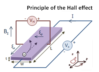
If a magnetic field is imposed from the side on a conductor through which current is flowing, the positive and negative charge carriers will migrate to opposite sides of the conductor, constituting a small but measurable voltage potential laterally across the conductor. This voltage is most evident when the conductor is a thin, flat rectangular plate. It arises only in the presence of the magnetic flux imposed from outside the conductor. Thus, the assembly, which has no moving parts, can function as a proximity sensor as well as a magnetometer. The output is in the low milliwatt range, so for many applications it is used in conjunction with an amplifier.
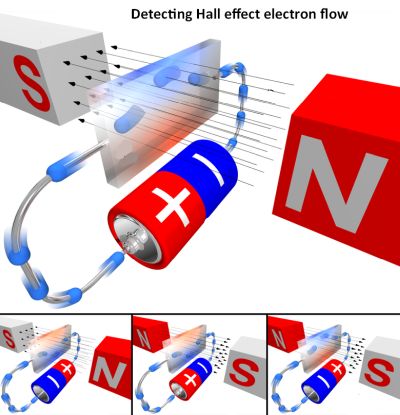
The Hall effect voltage also appears across a hole drilled in the plate, in response to electric current introduced at the edge of the hole. This second variation in the Hall effect manifests a change in output voltage (on or off) depending upon the polarity of the magnetic field. A bipolar sensor, as it is called, requires a positive (south pole according to current nomenclature) to energize the electric circuit. In contrast, a unipolar Hall effect circuit switches on and off as the sensor approaches or leaves the magnetic field. Here again, there are no moving parts. The only things that move are the external magnetic field or the entire Hall effect device. For this reason, unless they are subjected to overvoltage, Hall effect devices are generally maintenance free.
The Hall effect depends upon the motions of electrons, holes and/or ions. In the presence of a magnetic field, the charge carriers are subject to the Lorentz force, F, quantified as:
F = q(E + v×B)
Where q is an electric charge, E is the external electric field, v is the velocity of the charge, and B is the magnetic field, all in SI units.
Hall effect devices are used in many applications. An example is the clamp-on ammeter. Without the Hall effect device, this instrument is a simple transformer, which is not sensitive to dc. High-end clamp-on ammeters incorporate the Hall effect sensor to extend their functionality.
Hall effect sensors are currently available along with high-gain amplifiers in single integrated circuits. They can be sealed to make them immune to dust, dirt, mud and water. With no moving parts, the assembly is suitable for automotive applications including ABS braking systems, speedometers and electronic ignition and fuel injection systems.
Hall effect sensors can be built and configured to detect earth’s magnetic field. This property is exploited in some GPS systems. Tiny Hall effect sensors are installed on printed circuit boards and are used to provide feedback in variable-speed-drive-powered motor systems. Low-current sensitivity can be enhanced by introducing multiple turns in the current-carrying wire. In stationary installations, shielding can be used to reduce the effect of earth’s magnetic field. For circuits carrying higher amperage, a current divider is used. This consists of one thicker wire and one thinner wire, the thinner wire supplying the bias for the Hall effect device.
Servomotors frequently incorporate Hall effect sensors to keep track of the rotor position. The latest backhoes, mining trucks, cranes and scissors lifts are equipped with Hall effect joysticks, eliminating quantities of high-maintenance hydraulic hose.
A Hall-effect low-power thruster is used to propel some spacecraft once free of earth’s gravity. Magnets on the thruster accelerate ionized atoms. Neutral propellant is pumped into the chamber, where it is ionized by the electrons, creating plasma which creates sufficient thrust in the zero-gravity environment.
The Hall effect theory, originally laid out in the 19th century, is currently being revised to reflect recent developments in quantum physics. The imminent theoretician Klaus von Klitzing discovered that when a single layer of electrons in a semiconductor simultaneously saw low temperature and a high magnetic field, its intrinsic electronic property, Hall resistance, arose exclusively at integer multiples of h/e2, now called the von Klitzing constant. This is basically a quantized version of the Hall effect, observed in two-dimensional electron systems subjected to low temperatures and strong magnetic fields, in which the Hall resistance Rxy exhibits steps that take on the quantized values at certain levels Rxy=VHall/Ichannel = h/e2v where VHall is the Hall voltage, Ichannel is the channel current, e is the elementary charge and h is Planck’s constant. The divisor ν can take on either integer (ν = 1, 2, 3,…) or fractional (ν = ⅓, ⅖,3 ⁄ 7, ⅔, 3 ⁄ 5, …..)values.
It turns out there are real applications for the quantized version of the Hall effect. The quantization of the Hall conductance Gxy=1/Rxy is exceedingly precise. Actual measurements of the Hall conductance have been found to be integer or fractional multiples of e2/h to nearly one part in a billion. This phenomenon has allowed for the definition of a new practical standard for electrical resistance, based on the resistance quantum given by the von Klitzing constant. The quantum Hall effect also provides an extremely precise independent determination of a quantity of importance in quantum electrodynamics called the fine-structure constant.
By way of background, researchers had studied the 3D quantum effect since the mid-20th century, achieving success last year. The development is a theoretical electron model, which is expected to augment our knowledge of the 3D Hall effect. The latest iteration is a fractional version that dispenses with the magnetic field. In a cold 2D system with a strong applied magnetic field, the Hall resistance moves in discrete steps. The quantum Hall effect is not easily repeated because the energy is distributed in the direction of the applied magnetic field.
In 1987, the theoretician Bert Halperin suggested that a solution could be found if a gap could be opened in the material’s electronic structure. Examples could be an induced lattice potential or charge-density wave electrons falling into a standing wave. This would create an energy gap according to Halperin’s predictions:
1. Resistivity along the electric field would disappear, and
2. The Hall resistivity would remain at 2h/e2
This is how 3D quantum Hall effects would differ from 2D quantum Hall effects.
Despite subsequent research, Halperin’s predictions remain unverified. The problem involves 2D and 3D incompatibilities. Simply stacking 2D materials has not worked. The system seems to maintain 2D characteristics.
Fangdong Tang of the Southern University of Science and Technology and colleagues in China succeeded in observing the 3D Quantum Hall effect by using a 2T magnetic field in conjunction with 0.6 K cooling. The experiments exhibited suppressed longitudinal resistivity along with a Hall plateau at around 2.0 T. Because the Fermi wavelength was longer than the lattice constant, the researchers were able to state that the 3D Quantum Hall effect was due to a long wavelength as opposed to a crystal potential. The mechanism underlying the observed 3D Quantum Hall effect and an explanation for the Hall plateau at limited magnetic field levels remain unresolved. One explanation is that electron-phonon interactions cause the phenomena.
Following the discovery of the Quantum Hall effect, new experimental results continue to emerge. Researchers hope to find new materials that will exhibit the 3D quantum Hall effect. Two intriguing possibilities are that the 3D quantum Hall effect will be achieved at room temperature and without an external magnetic field.


Leave a Reply
You must be logged in to post a comment.