by Ben Robinson, National Instruments Corp.
Bandwidth isn’t necessarily the primary spec for evaluating how well a scope can display signals of interest.
Oscilloscope vendors, National Instruments included, like putting big numbers on the front panels of their instruments to tell you how much better they are than competitors. Bandwidth, sample rate, and sometimes bits-of-resolution are numbers vendors use to position themselves. Are the numbers on those front panels actually getting you better measurements with more insight as to the entity you are testing?
Not every measurement needs many gigahertz of bandwidth or gigasamples of data. As opposed to shopping for more bandwidth, often you can benefit more from oscilloscopes with better measurement accuracy and repeatability.
Bandwidth is usually the number-one specification you scan when looking at the list of available oscilloscopes. Generally, it is understood that the more bandwidth you can get on your scope the better. In many cases, however, the extra bandwidth doesn’t add significant value. For instance, a signal with rise time of one nanosecond requires about 350 MHz of bandwidth, according to the rule of 0.35 divided by bandwidth. Measuring that rise time with 5 GHz of bandwidth does not add a significant value.
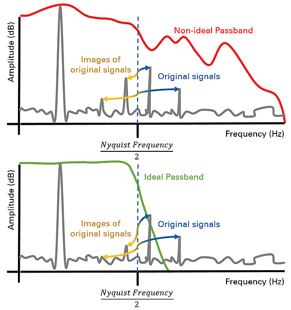
The bandwidth specification also does not tell you how good an oscilloscope is at rejecting high-frequency signals. The bandwidth spec on your scope doesn’t mean that signals above the instrument bandwidth disappear. It tells you only the frequency at which 70% of the signal amplitude is still included in the measurement. Signals outside the frequencies that the scope can accurately depict may have enough power to affect the measurements.
The biggest discrepancy in most oscilloscopes is the difference between the number of bits in the analog-to-digital converter (ADC) resolution versus the number of actual measurement bits of resolution. Make sure to do the research on specifications that actually matter for getting good measurements before spending budget dollars on your next oscilloscope.
Effective Number of Bits
Most scopes sold throughout the history of the instrument have used 8-bit ADCs, meaning they have 28 voltage divisions in which to measure a signal’s amplitude. Recently, more and more engineers are realizing there is value in having higher measurement resolution in their oscilloscopes.
Imagine you are validating the performance of a board trace that is carrying a 3.1-V square wave, or digital, signal. What you don’t know is that there is a short between this trace and another trace on the board that is carrying a low-voltage, 10-mV square wave. This kind of signal might also be a product of crosstalk between traces.
In many cases, you won’t know the exact resolution you’ll need for the measurement beforehand. If you knew there was a 10-mV signal imposed on the line, the measurement would be unnecessary.
A way to approach making the right decision for your instrument is to consider the highest and lowest amplitude signals in your system. What will be the resolution of the smallest signal in your system when you measure it using the largest necessary voltage range?
The following basic relationship can help you determine the resolution necessary to see these small signals in the system:
Radc = log10((Fmr/(Rr × Fsi))/2)
Where Radc = ADC resolution, bits;
Fmr = full scale of measurement voltage range, V;
Rr = required measurement resolution, V;
Fsi = full scale of signal of interest, V. For the example at hand with a 3.1-V square wave,
Radc = log10((10/(0.01 × 3.1))/2) = 8.33 bits
In this example, the equation shows that the oscilloscope should have an ADC resolution of at least 8.33 bits. Determination of the measurement resolution necessary in the system is just one step in seeing the details. What the equation does not say is that the equivalent number of bits of resolution is important. This number is usually somewhat lower than the physical number of data lines provided by the ADC.
Effective number of bits (ENOB) is a specification that relates measurement performance of an oscilloscope to a common specification used in data converters: bits of resolution. Instrument vendors have always used the data converter design to define the measurement resolution of their devices. However, no instrument or data converter is ideal, so it takes more characterization and understanding to determine the quality of an oscilloscope’s measurements.

ENOB is calculated directly from the signal-to-noise-and-distortion ratio (Sinad), a specification that includes all noise and measurement distortions from the instrument that appear within a measurement. ENOB then compares the performance of an ideal ADC to the ADC in a particular oscilloscope with the SINAD specification:
Enob = (Sn – 10log10(3/2))/20log102
= (Sn – 1.76)/6.02
where Enob = ENOB; Sn = Sinad.
A device that has an ENOB specification close to the resolution specification of the data converter would be ideal. In this example, the equation for ADC resolution showed a required measurement resolution of 8.33 bits. An eight-bit oscilloscope will not work. The best 10-bit scopes have an ENOB of approximately seven bits. In this example we would likely need to resort to a 12-bit oscilloscope. An ENOB of nine bits or better is typical of a 12-bit scope.
The oscilloscopes used for the measurements in this example are the PXIe-5162 (10-bit oscilloscope), PXIe-5122 (14-bit scope), and PXI-5922 (18-bit scope). The PXI-5922 can measure using between 16 and 24-bit resolution depending on sample rate. When the signal in our example with its imposed 10-mV square wave is measured with the 10-bit scope, the signal looks like noise. There is no way an observer would see the 10-mV signal. When measured with a 14-bit scope, it is clear there is a periodic signal superimposed that is likely a square wave. The measurements taken with an 18-bit scope show the signal is a square wave and give accurate measurements of that small signal.
However, there are more trade-offs than just measurement clarity with high resolution. The 18-bit scope used to perform the measurements above includes a high-resolution delta-sigma (Δ∑) or sigma-delta (∑Δ) ADC. A delta-sigma ADC has high linearity and is sensitive to small changes in signal amplitude, but does not accurately measure large, fast changes in amplitude. You can see in the measurement taken with the 18-bit oscilloscope that there is significant ringing after the edge of the large (3.1 V) transition.
An instrument with higher ENOB provides a number of benefits to testing:
• When a single measurement contains significantly more data about the behavior of the signal, you can spend less time setting up and configuring the test station to record data and more time analyzing your records for the data that matters.
• When you can get more information while designing the product, you can troubleshoot and redesign faster than your competition. Better measurements mean less time in characterization, validation, and specification-setting and less time to market.
• Most designs require specifications with a high confidence in performance. The more resolution and accuracy your instrument has when creating these specifications, the more confidence in your design.
• More accurate measurements mean better test results and more confidence for a test engineer ensuring that the final product works properly.
ENOB is defined, in large part, by the ADC used in the design of the scope. An ADC and architecture that has the right time-domain jitter performance and spectral noise density, along with many other specifications, ultimately determines the measurement quality of the instrument. In this case, hardware is the absolute determining factor of the scope’s specifications. But that is not the case for many specifications of modern scopes.

As scopes become increasingly sophisticated, many specifications are based on software-defined components like digital signal processors (DSPs) and FPGAs. An increasing number of scope vendors offer packages that add more options for firmware design. Many of these packages provide different types of filters (like Bessel, Butterworth, or Gaussian) optimized for specific behaviors like faster rise time or limiting overshoot.
Some vendors even offer firmware design packages that permit making changes directly to the scope’s filter and trigger designs. For many, you must be familiar with DSP and FPGA programming tools to make the changes. Other scope firmware design environments have graphical programming or flowchart interfaces that are more accessible if you know FPGA programming languages like VHDL and Verilog.
Firmware design packages that provide access to filter and trigger designs let users tailor scopes for specific measurements. In some cases, scope makers open unused portions of the FPGA to implement signal processing, new triggering logic, and even data streaming interfaces. Although firmware design cannot change every specification, it can certainly empower you to extend or optimize a scope to get the most accurate and reliable measurements.
References
National Instruments Corp.,
www.ni.com

Leave a Reply
You must be logged in to post a comment.