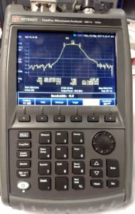
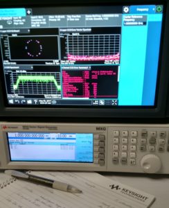
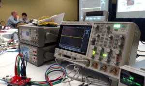
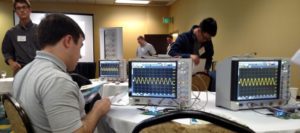
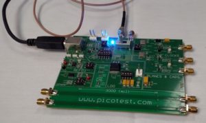
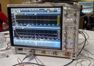
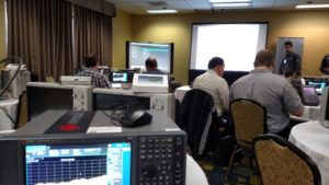
Photo gallery: Here’s what happens during Keysight’s Test-drive 2017 May 2, 2017 By Lee Teschler Leave a Comment Instrument maker Keysight is conducting what it calls a North American test-drive tour at 30 cities in the U.S. and Canada this spring. We sat in during the stop in Cleveland, Ohio. Here’s what we saw. The seminar kicks off with a sort of RF-For-Dummies review of modulation and tx/receive fundamentals. Each two attendees get the use of a FieldFox portable RF analyzer and an EXA/MXA signal analyzer. The labs in the seminar are pretty much idiot-proofed thanks to Keysight personnel floating around among the tables. The first lab of the day had us doing a sweep to measure the bandwidth of a band-pass filter. The main trade-offs of the FieldFox we used, compared to bigger bench analyzers, is a lower scan time, higher noise floor, and lower dynamic range. A lot of the morning is spent playing with the Keysight X Series spectrum analyzer driven by a vector signal generator. In this exercise we demodulated an LTE signal — a personal treat for your humble narrator who had never seen a QAM constellation plot in the flesh. Other exercises included measurements of signal phase noise, adjacent carrier power, and things you could do to lower the noise floor. The red gizmo in the bottom left corner of the image is a daughterboard on top of an Arduino. The contraption is meant to mimic generic wearable consumer electronics for the low-power measurement lab that takes place after lunch. We got a chance to use 4-wire sensing from the dc supply seen at right, as well as make low-current measurements on a wave-displaying DMM and a scope. We also made use of the mixed-signal scope to do some high-speed digital analysis and to debug a mixed signal using zone triggering. This section included a demo of BenchVue software run by a Keysight instructor. The final segment of the day covered power integrity measurements using the Infiniium S-Series scope. The intro covered the reasons why you often need to look at the hash riding on the dc level coming out the dc rails: Turns out the no. 1 cause of clock/data jitter is power supply noise. Here’s what we used to simulate a dc supply plagued by noise. We measured parameters both using a plain-jane 50-Ω passive probe and a high-impedance model (N7020A) to see the difference. One of the nice things about the Infiniium S-series is the ability to run an FFT on the waveform of interest as a way to characterize the noise frequencies present. This is one of the last things we did before Keysight ended the day by raffling off an oscilloscope.
Leave a Reply
You must be logged in to post a comment.