Most high-spec contemporary oscilloscopes include as an option a built-in arbitrary function generator. Engineers use this feature on a daily basis. It goes well with the many other capabilities in today’s amazing digital storage oscilloscopes, and one would not want to be without it.
However, a well-equipped bench will usually have a stand-alone arbitrary waveform generator. Its cost and bench-space requirements are modest, and there are numerous features contained in the small enclosure.
The ancestor of this device was known as a signal generator, a large relatively heavy instrument in a metal enclosure. In the post-World War II electronics boom, TV servicing was big business, and the local shop invariably had a signal generator to inject signals into RF, IF and audio or video sections. Oscilloscope probes could then check outputs, using the schematic, block and pictorial diagrams to navigate.
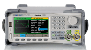 As electronic equipment became at once more varied and capable, far more advanced arbitrary waveform generators emerged. We’ll consider a contemporary example, the Siglent SDG 2122X Function/Arbitrary Waveform Generator. To really explore the vast capabilities of this elegant instrument, we will want to connect it to an oscilloscope. Two BNC cables are needed to connect the two Siglent outputs to the Channel One and Channel Two analog inputs of the oscilloscope, so the signals can display simultaneously and can be made to interact.
The Siglent arbitrary waveform generator has a 4.3-in. screen that displays either of the two outputs, not both simultaneously. To clarify, the two outputs can at any given time be active and can be displayed in the connected oscilloscope, but only one of them at a time can be displayed in the arbitrary waveform generator. Moreover, they do not interact in the arbitrary waveform generator. It is the oscilloscope that performs that function.
Though the two channels cannot be displayed together in the arbitrary waveform generator, it is a simple matter to toggle between the two. Use the button on the front panel that is labeled Channel Select Key.
The two signals can be selected from internally generated waveforms or from user-created arbitrary waveforms, and parameters of each can be customized. These settings persist even when the instrument is powered down between work sessions. It doesn’t matter which of the two is selected for display, nor whether one or both outputs are temporarily toggled off.
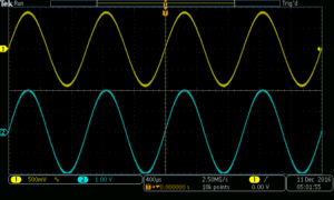
Now that both signals are in the oscilloscope, they can be made to interact in a number of ways. One way is accomplished by pressing Math in the oscilloscope and then the soft key associated with Dual Waveform Math. The first source is set on channel one and the second source is set on channel two. The operator can be shifted to add, subtract, multiply or divide. Moreover, going back to the Siglent Arbitrary Waveform Generator, the phase of one or both waveforms can be set to any value between 0 and 360°. Then, the red resultant trace in the Dual Waveform Math facility acts differently, as may be expected.
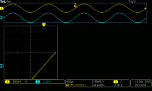
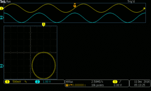
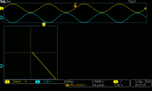
Another enlightening exercise that also involves the signals from both channels is the creation of Lissajous patterns. To do this, we leave the Math function in the oscilloscope and press Acquire. The acquisition menu includes XY Display, which is currently in the default off state. Pressing the associated soft key, the XY submenu appears at the right side of the display. To turn on the XY display, press the soft key associated with Triggered XY. The Lissajous pattern appears in the lower left quadrant of the display. To make things still more interesting, toggle YT to On so the two waveforms appear at the top of the display in split-screen format. The Lissajous pattern created by two signals that are in phase is a straight diagonal line, sloping from the bottom left to the top right.
Other capabilities of the waveform generator are best shown when feeding a single signal to the oscilloscope. To do this, turn off Output Two in the Siglent and Analog channel two in the oscilloscope, just to keep everything organized. Once again, in the arbitrary waveform generator, press Waveforms and then Sine. Then press the Modulation key.
This action opens up a whole new world, where a high-frequency carrier is modulated by a lower-frequency information-bearing signal. In the upper portion of the arbitrary waveform generator display, the modulated carrier waveform is shown along with its parameters. In the lower part of this display, the amount of modulation in percent appears as well as the frequency. All of these values can be altered using the keyboard. Parameters of the modulating signal, including percent of depth for AM modulation, can be set in the lower part of the display. The waveform as modulated appears in the oscilloscope display.
Types of modulation, which may be chosen from a menu at the bottom of the arbitrary waveform display, include AM, FM, PM, FSK, ASK, DSB-AM, PSK and PWM (Pulse Width Modulation). Pulse Width Modulation is of great importance on the factory floor where variable frequency drives use it to control speed, torque qualities, and other aspects of three-phase induction motors.
Another interesting capability of the arbitrary waveform generator is seen when we press the Sweep button. At first this action may not seem to do anything in the oscilloscope though the arbitrary waveform generator displays a white line through the sine wave in its display indicating the instrument is outputting a swept waveform, i.e. varying the frequency at a prescribed rate. To make this dynamic display appear in the oscilloscope, you have to set the frequency rate of the basic waveform to a reasonable level. Sixty Hertz works well. At higher frequencies, the sweep information is too fast for the oscilloscope update rate.
Another mode that can modify the sine wave is Burst. To display it in the oscilloscope, press the burst button on the front panel of the arbitrary waveform generator. In telecommunications, a burst segment is a high-bandwidth fragment that happens at a specific, often recurrent, time location along the X-axis when the instrument is operating in the time domain. Implicit is the idea that the data is highly compressed.
In the Siglent SDG 2122X Arbitrary Waveform Generator, the burst function can be precisely controlled. The duration of the burst can be set at a specified number of cycles or a burst can be made to happen when an external gated signal is applied. It may be inserted into any waveform, which is then known as a carrier, except for dc. Noise can be used as a carrier only in the gated mode.
This arbitrary waveform generator, because it is a digital instrument, can store and recall its current operating state as well as user-created arbitrary waveforms in internal or external memory. To perform this operation, press the Store/Recall button on the front panel. The relevant menu displays. The Siglent Arbitrary Waveform Generator contains an internal non-volatile memory, C Disk. Alternately, data may be saved to an external medium such as a flash drive, which is inserted into the USB slot on the front panel.
To save the instrument state or data, such as a displayed waveform, press save. Similarly, files can be named, recalled, deleted or copy and pasted. When the flash drive is inserted into a computer USB slot, its contents can be edited and saved in a variety of useful ways.

Leave a Reply
You must be logged in to post a comment.