The object of signal compression is to facilitate transmission, reception, processing, and the use of great amounts of data while conserving valuable storage space and transmission resources. Data compression is obviously a good approach provided that it doesn’t incur an unacceptable amount of information loss.
It was once widely assumed that detail or information, once lost, could never be recovered. But lossless (as opposed to lossy) compression methods have emerged. This development is relevant and useful in the fields of image and audio compression.
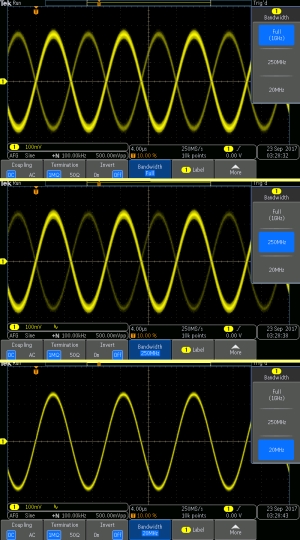
Bandwidth compression is technically quite simple. Higher portions of an information-carrying signal can easily be eliminated by means of a low-pass filter. In its simplest form, this filter is a capacitor inserted across the source. An elementary demonstration of bandwidth limiting in a Tektronix MDO3000 digital storage oscilloscope consists of the following:

Start the instrument and activate the arbitrary function generator. The default sine wave appears in the display. Press Output Settings and add 20% noise, enough so that triggering is lost and the trace contains a measure of noise. Then press the LED button associated with the active channel. Press the soft key corresponding to Bandwidth, which brings up that menu. The default bandwidth is, of course, the full bandwidth of the instrument, printed on the front panel. Bandwidth can be limited to a medium or low value by pressing soft keys, and this partially or fully restores triggering and eliminates noise, a broad-spectrum phenomenon.
This is the basic principle of bandwidth compression, where the bandwidth of an information-carrying signal is purposely limited.
Data compression involves the information content of the original signal rather than the equipment for conveying the information. This type of compression can be lossless. In this instance, the number of bits is reduced by eliminating those that are redundant. As the name implies, no information is lost in this type of compression. In contrast, lossy compression involves eliminating bits that are less important from the point of view of the end user and which do not suit the goals of the sender. Nevertheless, they are a real part of the original signal. There is a loss but ideally, it is not damaging.
An example from the field of acoustics is in music or voice transmission. It consists of eliminating frequencies that are not audible because they are outside the human range, generally considered 20 Hz to 20 kHz.
Lossy data compression is as much an art form as a science because it involves multiple tradeoffs. Examples include the degree of compression, the amount of distortion that is introduced, and cost in hardware and software to accomplish both compression and at the receiving end, decompression.
Dynamic range compression has the same basic priorities. But it pertains primarily to audio transmission and reproduction. Rather than bandwidth, it is dynamic range that is reduced. By this it is meant that low-volume sounds are amplified and high-volume sounds are attenuated. This action defines dynamic range compression.
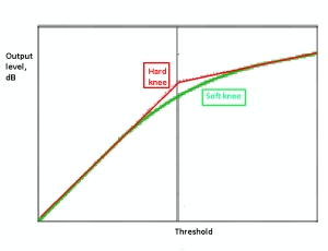
Dynamic range, and hence file size of an audio signal, can be limited by either downward compression or upward compression. First, the desired threshold is selected. Downward compression attenuates loud sounds over that threshold without affecting the volume of sounds below that threshold. Upward compression amplifies the volume of signals below that threshold without affecting the volume of signals above that threshold. So we see that what bandwidth compression is to frequency, dynamic compression is to amplitude. Both take out the extremes, thereby reducing file size.

In dynamic compression, a graph can be plotted by drawing a line that shows the output level in dB on a vertical axis and the input level on a horizontal axis. The upward-sloping line consists of two portions, one above the threshold and one below. At the threshold, the slope of this line changes at a location known as the knee, where the line crosses the threshold. In addition to setting the threshold, the audio editor can choose a hard knee or a soft knee, which determines the abruptness of the angle where the line segments join at the threshold.
Gain compression is generally an unwanted and harmful effect that happens in RF and audio amplification. It was first noticed back in the time when vacuum tubes were used in amplification. This type of compression is a consequence of power dissipation and heat caused by driving an amplifier into a non-linear portion of its dynamic range. The end result is a reduction in differential gain accompanying non-linearity of the amplifier’s transfer function. In transistorized circuits, gain compression is less acute but to some degree, it can be an issue. In radio receivers, if the RF section is overloaded, gain compression will appear as distortion in the final audio signal. In the non-linear portion of the response curve, the waveform will be altered in both tube and transistor sets.
Besides this unintended and harmful variety of gain compression, the same phenomenon can be intentionally used to good effect in automatic gain control (AGC). The device that enables AGC is called a dynamic range compressor. You may have noticed when tuning a radio receiver to a frequency not in use that the background noise rises in volume. That is AGC at work. Similarly, prominent snow is seen on a TV screen when the set is tuned to an unoccupied channel. A related effect shows up as the noise floor in an oscilloscope or spectrum analyzer when there is no signal at the input and Autoset is pressed. The instrument is looking in vain for a signal and seeing only its own internal thermal noise.
Image compression is a vast, highly detailed subject. Specialized algorithms, as opposed to general compression methods, are employed because, among other reasons, there is a large quantity of detail in image transmission and any distortion that accompanies lossy compression will severely compromise the end product. The goal in image compression is to reduce storage and transmission costs.
One way image compression is quantified is with an image compression ratio. This ratio R is calculated from the ratio of the original to the compressed image size. The original image size A = (original width)×(original height)×(no. of color planes)×bit depth/8. Here the image dimensions are in pixels and the 8 is the number of bits in a byte. If the size of the compressed image B is in bytes, then the compression ratio is R = A/B.
Lossless image compression is the method of choice for sensitive applications such as medical imaging and glossy print publications where high resolution is essential. For websites, a higher degree of loss is acceptable because the limiting factor is the computer monitor. Popular lossless image compression methods include GIF, TIFF, PNG, MNG and TIFF. Methods for lossy image compression are color space reduction, chroma subsampling, transform coding and fractal compression.

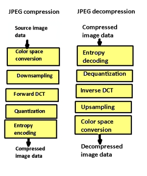
transform. Entropy coding is a lossless coding scheme that compresses digital data by representing frequently arising patterns with few bits and rarely occurring patterns with many bits.
Transform coding is widely used. It involves a Fourier-related scheme such as the discrete cosine transform. A related compression method is enabled by the wavelet transform. The basis for this type of compression is that the wavelet transformation permits changes in time extension, but not shape. A higher required time resolution permits a lower frequency resolution. Wavelet compression is superb for image compression including video as well as audio applications.
Wavelet compression works well for processing brief transients. Examples in audio include near-instantaneous drum sounds; an example in graphics is celestial images such as pin-point stars. Other compression methods could erase these small transients.
The discrete wavelet transform is also suitable for compressing electrocardiograph signals, where loss of brief transients in the form of spikes could result in loss of the patient. Waveform compression is not as suitable for smooth, periodic signals, where frequency domain representations by means of Fourier transforms are better.
A useful image compression method is JPEG (Joint Photographic Experts Group). It is minimally lossy, capable of achieving 10:1 compression with only a slight reduction in image quality. JPEG imaging is one of the formats used in digital photography, and it has been successful on the Web. The file name extension is .jpg. One of the good things about JPEG is that the degree of compression and hence image quality is adjustable by the user on a case-by-case basis.
JPEG is based on the discrete cosine transform (DCT), which can convert each frame of a video source from the time domain to the frequency domain using the Fast Fourier Transform. By means of quantization, JPEG models human perception, rejecting high-frequency information such as fast imperceptible intensity and color transitions. That is what accounts for the ability of JPEG to provide high degrees of compression with little compromise in image quality.

thanks for the information