Several tricks can help reveal small signals that are obscured by measurement system noise.
KENNY JOHNSON
KEYSIGHT TECHNOLOGIES, INC.
THERE is a need to observe small signal details in many modern applications. Transducers, biomedical sensors, high energy physics, power integrity, and high-speed digital designs are examples of situations where details can be obscured by measurement system noise. Measurement system noise is the noise of the oscilloscope, probes and connection method that is superimposed on the signal of interest.
When the signal being observed is small, like the ac ripple and noise on a power supply, the signal presented on the screen of the oscilloscope may only vaguely represent what is real if care is not taken to reduce measurement system noise. The complete elimination of measurement system noise is not a realistic goal though there are some practical steps that can be taken to substantially reduce it.

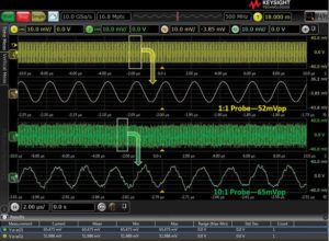
There are two primary sources of noise in an oscilloscope-and-probe system. The input amplifier and buffer circuits in the scope contribute some noise, and the probe amplifier of an active probe has its own noise. Scopes use an attenuator to vary the vertical scale factor. The scope’s noise arises after this attenuation. When the attenuator is set to something greater than 1:1 (the scope’s most sensitive hardware range) the noise will appear to be larger relative to the signal at the input connector of the scope. Consider a scope that has a basic sensitivity of 5 mV/div with no attenuation inserted (1:1). For this example, we will say this scope has a noise floor of 500 µVrms at 5 mV/div. If we change the sensitivity to 50 mV/div the scope inserts a 10:1 attenuation in series with the input. The noise then appears as if it were 5 mVrms relative to the input (500 µV×10). The same thing happens when a probe with attenuation is attached to the scope. The scope noise appears larger relative to the signal at the input to the probe by the amount of the attenuation.
One obvious suggestion is to choose the low-noise path. Unfortunately, many users stumble here, not knowing they may have even better options available to them. The oscilloscope measurement path consists of the oscilloscope being used and the scope input termination—50 Ω or 1 MΩ. For many oscilloscopes, the 50-Ω input is a lower-noise path than the 1-MΩ path.

A measurement of the baseline noise of the oscilloscope measurement system is a sanity check similar to shorting the leads together on a DMM before making a continuity or resistance measurement. It is a good practice to perform what’s called a null measurement on the complete oscilloscope measurement system—including probe and connection accessories—to be confident that the oscilloscope, probe and connection method are appropriate for the measurement about to be undertaken.
To make a null measurement simply configure the oscilloscope and probes as they will be used during the measurement, including sensitivity (volts/division) and time base (time/division), then short the probe input to ground (or short the inputs together on a differential probe) and measure the noise. If the results from the null measurement are not acceptable, it may mean that a different oscilloscope, probe, or connection method needs to be used.
Bandwidth limits
More bandwidth is better, right? Not always. The noise voltage of an oscilloscope, probe, and connection accessory are a function of frequency. Limiting the used bandwidth to only the amount necessary for the given measurement will reduce the amount of oscilloscope, probe and connection noise that shows up in the measurement.

Oscilloscope manufacturers recognize the need to adjust bandwidth to make different measurements and have provided a variety of bandwidth limit presets. Some manufacturers also provide the ability to set any bandwidth limit to further tailor the limits to the measurement. If a desired preset or adjustment is not available a math function can be implemented to filter the signal, though this can reduce throughput because there are calculations performed on each acquisition.
To use this filtering technique, one must know the amount of bandwidth necessary for the signal of interest. There are resources available on oscilloscope manufacturer websites that explain, in depth, how to determine the needed bandwidth. In summary, for digital signals, the necessary oscilloscope bandwidth is 2X the signal bandwidth. The signal bandwidth can be calculated from the rise time of the signal: signal bandwidth = 0.5/rise time.
If the signal of interest is not digital or is of an unknown source, like noise on a power rail, there’s an alternative approach. In this case, the signal is probed at the full bandwidth of the measurement system and observed in the frequency domain via an FFT (Fast Fourier transform) to see the frequency at which the signal content diminishes. A bandwidth limit can then be set at or near the frequency observed with the FFT.
Oscilloscope probes can have an impact on noise. Probes come in a variety of attenuation ratios. Probably most familiar is the 10:1 passive probe. One benefit of using a 10:1 probe is that it allows the measurement of signals that otherwise would exceed that maximum input to the oscilloscope. The down side of attenuation is that the scope noise relative to the size of the signal being measured increases proportionally to the attenuation ratio.
Fill the screen
Oscilloscope noise, resolution, and accuracy are a function of the full-screen voltage or volts-per-division. It is a good practice, then, to always expand the signal being measured to fill the whole screen of the oscilloscope. This not only minimizes the amount of oscilloscope noise but also improves accuracy and resolution.
Accuracy is commonly 1-2% of the full-screen voltage. Taking an eight-bit A/D as an example, the resolution is the full-screen voltage divided by 256 (28). A “bad habit” that many users have is when viewing more than one signal on-screen, they will scale each signal so the signals do not overlap and are easier to see rather than creating individual windows or graticules for each waveform.


Noise can impact probe use in another way: Oscilloscope probes usually come with a wide variety of connection accessories to accommodate various targets and improve ease-of-use. For example, probes come with a variety of ground leads and ground clips. The long ground leads are included as a way of making convenient qualitative measurements like checking that data lines are toggling or that a supply is up. When making important, quantitative measurements like rise time, overshoot, ripple, et cetera, the shortest ground connection possible should be used. External noise sources can couple in the loop of the ground connection. The smaller the loop area of the ground connection the less susceptible it is to picking-up external noise.
If the signal of interest is repetitive and there is no desire to capture transient events, then averaging is an effective method of reducing noise. Averaging is an acquisition mode where the oscilloscope overlays or averages a predetermined number of acquisitions into one waveform. Over multiple acquisitions, random noise will be averaged-out resulting in a crisp view of the signal.
Another noise-reduction option available on some oscilloscopes is “high-resolution” mode. This mode is like averaging in the way it reduces noise, yet it can be used on non-repetitive signals. High-resolution mode averages together multiple adjacent sample points of a single acquisition to create a single sample point. In this way, it averages out the effects of random noise on the signal captured by the oscilloscope. The limitation to high-resolution mode is that it reduces the bandwidth of the measurement.

For example, if an oscilloscope sampled data at 8 GSa/sec its Nyquist bandwidth would be 4 GHz. If the same oscilloscope averaged together four adjacent points to create one new point in high-resolution mode, its effective sample rate would be 2 GSa/sec and its Nyquist bandwidth would be 500 MHz.
In a nutshell, there are multiple, easy-to-implement techniques available to help measure small signals or signals where measurement system noise can be troublesome. Sometimes only one or two techniques — like filling the screen or limiting bandwidth — are enough. However, it is good to be aware of all these techniques for occasions when more challenging conditions present themselves.
REFERENCES
HOW TO DETERMINE HOW MUCH BANDWIDTH YOUR SCOPE NEEDS


Leave a Reply
You must be logged in to post a comment.