A radar test system from Rohde & Schwarz simulates driving scenarios for testing radar based advanced driver assistance systems (ADAS) and radar sensors used in autonomously driving cars (AD) entirely over the air.
The test solution consists of the new R&S AREG800A automotive radar echo generator as a backend and the 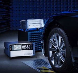 R&S QAT100 antenna array as a frontend. Laterally moving objects, i.e. objects approaching from the side, are currently simulated by mechanically moving antennas. The R&S RTS replaces the mechanical movement by electronically switching individual antennas in the frontend on and off. Even objects moving laterally to the car at high speed can be simulated reliably and reproducibly. The R&S RTS is able to simulate the radial velocity (Doppler shift) and the size (radar cross section) of objects at user configurable–including very small–ranges. Countless objects can be represented by cascading multiple R&S AREG800A backends. The R&S RTS moves tests currently performed on the road to the lab. This allows early error detection and a significant reduction in costs.
The new R&S RTS–consisting of the R&S AREG800A backend and the R&S QAT100 antenna array frontend–is a target simulator that generates dynamic radar echoes that can be used at all stages of automobile radar sensor testing–from pre-development through hardware-in-the-loop lab tests to validation of ADAS/AD functions integrated in the vehicle. The backend can simulate a large number of independent artificial objects and dynamically vary their range, size (radar cross section) and radial velocity. With an instantaneous bandwidth of 4 GHz between 76 GHz and 81 GHz, it covers the typical frequency range of current and future automotive radar sensors.
The frontend uses up to 192 independently switchable antennas to simulate objects moving laterally to the car’s direction of movement, providing very fine resolution, high switching speed and high repeatability. Electronic switching of the antennas does not cause any wear to RF cables and other moving parts, as is otherwise encountered with mechanical antenna motion used in traditional test systems.
An optional transmit array makes it possible to simulate two objects close together and moving laterally to the car. The small patch antennas and the absorber-lined surface provide a low-reflection RF frontend with a very small radar cross section. This reduces the sensor’s noise floor and suppresses close-range targets and potential multipath reflections. The antenna spacing of just 3.7 mm delivers fine angular resolution. Multiple frontends can be combined to cover larger fields of view of radar sensors. An angular resolution of less than 0.5° is possible.
Starting from simple scenarios such as automatic emergency breaking (AEB), the R&S RTS can be extended to cover complex scenarios with multiple radar sensors thanks to its modularity and scalability. Any number of R&S QAT100 frontends and R&S AREG800A backends can be combined. One of the backends synchronizes all the components installed in the setup. A graphical user interface with a touchscreen makes it easy to configure the test setup.
For test automation with industry-standard tools, the R&S RTS comes with a hardware-in-the-loop (HiL) interface conforming to the ASAM Open Simulation Interface specification.
Rohde & Schwarz, 6821 Benjamin Franklin Dr, Columbia, MD 21046, (410) 910-7800, www.rohde-schwarz.com


Leave a Reply
You must be logged in to post a comment.