• Skip to primary navigation
  • Skip to main content
  • Skip to primary sidebar
  • Skip to footer
  • Advertise
  • Subscribe

Test & Measurement Tips

Oscilloscopes, electronics engineering industry news, how-to EE articles and electronics resources

  • Oscilloscopes
    • Analog Oscilloscope
    • Digital Oscilloscope
    • Handheld Oscilloscope
    • Mixed-signal Oscilloscope
    • PC-based Oscilloscopes – PCO
  • Design
  • Calibration
  • Meters & Testers
  • Test Equipment
  • Learn
    • eBooks/Tech Tips
    • FAQs
    • EE Training Days
    • Learning Center
    • Tech Toolboxes
    • Webinars & Digital Events
  • Video
    • EE Videos
    • Teardown Videos
  • Resources
    • Design Guide Library
    • Digital Issues
    • Engineering Diversity & Inclusion
    • Leap Awards
    • White Papers
  • Subscribe
You are here: Home / Oscilloscopes / Digital Oscilloscope / Rohde & Schwarz’s Digital Oscilloscope Enhances Performance of Embedded Systems

Rohde & Schwarz’s Digital Oscilloscope Enhances Performance of Embedded Systems

May 5, 2011 By Test and Measurement Editor Leave a Comment

Rohde & Schwarz has developed the industry’s only digital oscilloscope that employs a real-time digital trigger. Designated the R&S®RTO Series, the advanced scope significantly enhances productivity and product performance when debugging embedded systems.

The real-time digital trigger in the R&S®RTO Scope Series uses a common signal path for both the trigger and acquired data. This eliminates time and amplitude offset between the trigger and signal, enabling signals to be displayed with the least possible trigger jitter and allowing precise results to be achieved when measuring complex waveforms.
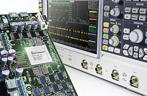
Analog triggers typically have a long re-arm cycle, and while re-arming, the instrument cannot react to trigger events, which means signal properties that should act as triggers are masked. Because the R&S®RTO Scope Series’ digital trigger does not need to re-arm, every sample can trigger data acquisition to avoid missing events.

In addition, errors in serial interfaces are often caused by sporadic signal faults at the physical layer, so high acquisition rates are essential in order to detect them. Since R&S®RTO Scope Series acquires and displays signals using hardware, blind time is minimized and errors are located quickly. Also, many embedded systems employ serial data interfaces to control external devices and simply viewing the waveform is not sufficient to fully debug the operation of these systems. The R&S®RTO features an integrated trigger and decode feature that allows users to trigger on protocol-specific features and to display the captured waveform in binary, ASCII or HEX formats. The trigger and decode feature supports SPI, I2C, CAN, LIN and RS232.

Rohde & Schwarz
www.rohde-schwarz.us

Filed Under: Digital Oscilloscope, Oscilloscopes Tagged With: digital oscilloscope, Rohde Schwarz

Reader Interactions

Leave a Reply Cancel reply

You must be logged in to post a comment.

Primary Sidebar

Featured Contributions

impedance plot

How physics relates signal integrity, power integrity, and EMC

Why engineers need IC ESD and TLP data

Verify, test, and troubleshoot 5G Wi-Fi FWA gateways

How to build and manage a top-notch test team

How to use remote sensing for DC programmable power supplies

More Featured Contributions

EE TECH TOOLBOX

“ee
Tech Toolbox: Sensors
In this Tech Toolbox, we cover some of those technologies driving the next generation of connected systems, including ultra-low-power sensing strategies that extend node battery life, and 60 GHz CMOS radar for contactless health and presence detection.

EE TRAINING CENTER

EE Learning Center
“test
EXPAND YOUR KNOWLEDGE AND STAY CONNECTED
Get the latest info on technologies, tools and strategies for EE professionals.
bills blog

RSS Current Electro-Tech-Online.com Discussions

  • Voltage comparator circuit verification
  • What is this???
  • Why aren’t the power windows in my 2006 Volkswagen Polo 2006 working despite repairing the control unit circuit board?
  • infiniBand Layer 1 specifications testing question
  • block RF

Footer

EE World Online Network

  • 5G Technology World
  • EE World Online
  • Engineers Garage
  • Analog IC Tips
  • Battery Power Tips
  • Connector Tips
  • EDA Board Forums
  • Electro Tech Online Forums
  • EV Engineering
  • Microcontroller Tips
  • Power Electronic Tips
  • Sensor Tips

Test & Measurement Tips

  • Subscribe to our newsletter
  • Advertise with us
  • Contact us
  • About us

Copyright © 2026 · WTWH Media LLC and its licensors. All rights reserved.
The material on this site may not be reproduced, distributed, transmitted, cached or otherwise used, except with the prior written permission of WTWH Media.

Privacy Policy