Some contemporary oscilloscopes, such as the Tektronix MDO3104, may incorporate an optional built-in arbitrary function generator (AFG). This is an enormously useful and convenient feature, either as a replacement or a supplement for a stand-alone bench-type AFG.
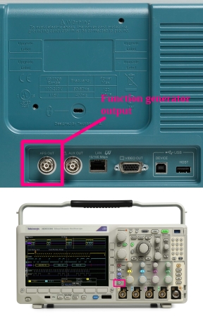
In the Tektronix instrument, there are 14 available waveforms, ranging from sine wave to cardiac. The AFG output is accessed from a BNC jack on the back panel. A BNC cable can be run from there to one of the analog inputs on the front panel or to an analog input on another oscilloscope. Do not, however, succumb to the temptation to cut off one of the BNC ends so the waveforms can be put to creative uses, because the oscilloscope will not tolerate a short circuit or heavy load, such as an 8-Ω speaker, connected to the AFG output.
When AFG is pressed, the AFG menu appears across the bottom. Pressing the soft key corresponding to output settings opens a vertical menu to the right. The second item from the top is Add Noise. Noise can be added to any of the waveforms.
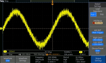
When the associated soft key is pressed, we see that the default amount of noise is 0.00%. It can be adjusted using Multipurpose Knob a, with Fine disabled. It is quicker to use the keypad if you know the percentage of noise you wish to add. All noise can be quickly removed by pressing 0 on the keypad.
A useful AFG menu item is Waveform Settings. First, change the waveform to Square, for reasons that will soon become clear. Then press the soft key associated with Waveform Settings.
The first menu item has two entries, frequency, which can be set by turning Multipurpose Knob a, and Period, which can be set by turning Multipurpose Knob b. These two metrics are inversely related. When either of these is increased by turning the appropriate Multipurpose Knob, the other drops.
Frequency in electronics is defined as the number of complete cycles arising per second of an oscillating or varying current. This includes both the positive-going and often mirror-image negative-going portions of the waveform.
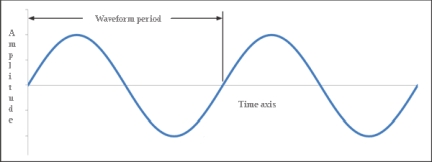
Period in electronics is defined as the interval of time between successive occurrences of the same state in an oscillating or cyclic phenomenon, particularly alternating current or an electromagnetic wave.
Referring to the square wave, when we increase the frequency using Multipurpose Knob a with Fine disabled, notice that the high and low portions of the waveform become shorter in duration and the period drops. Also, more cycles appear in the display because the time base remains the same.
Using the keypad, it will be found that the maximum frequency that the Tektronix MDO3104 AFG can output is 50 MHz. This is the same for the sine wave, but it varies for some of the other waveforms.
Returning to the square wave shown at its default frequency, we’ll press Waveform Settings. Notice that the default duty cycle is 50%.
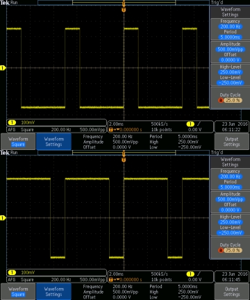
The definition of duty cycle in electronics is the amount of time that a given portion of the waveform (usually the most positive) is active, expressed as a percentage of the entire period. Duty cycle is applicable only to digital type signals such a square wave and pulse, in which latter case the duty cycle is expressed as pulse width and given in units of time. Duty cycle is not applicable to analog signals such as sine. When Sine Wave is accessed in the AFG, Duty Cycle does not appear as one of the menu items in Waveform Settings.
Pressing the soft key associated with Duty Cycle, we see that the duty cycle can be altered by turning Multipurpose Knob a or by using the keypad. The highest duty cycle that the AFG can synthesize is 90%, and the lowest is 10%.
The square wave frequency and duty cycle are independent variables. In other words, either of these can be changed without modifying the other.
Duty cycle as it relates to electronic waveforms is used on factory floors and tall buildings with elevators worldwide. AC motor speed is almost universally controlled by pulse-width modulation. The main difference between a square wave and a pulse wave is that the square wave is usually symmetrical with respect to the X-axis (0 V). The low and high voltages are quite often numerically the same with opposite polarities. Pulse waves, in contrast, usually bottom out at zero or some low voltage.
Variable Frequency Drives (VFDs) make use of pulse-width modulation to regulate the speed of AC induction motors. Before the invention and widespread use of VFDs in the mid-twentieth century, motors in sensitive applications, such as ski lifts and elevators requiring smooth speed regulation, were predominantly dc though rectifiers or motor-generators were required to power them.
AC induction motor speed can be reduced to a certain extent by lowering the supply voltage, but this is not a good solution because in such a situation the motor is overloaded. It will run hot and have a shorter life.
VFD technology slows an AC induction motor by running it on an AC-pulsed waveform where the pulse width is modulated so that it is narrowed, without reduction of the amplitude. By widening the pulse width, the motor can actually be made to turn faster than rated RPM. (In both instances, bearings and fan cooling must be considered.)
Often, an ordinary off-the-shelf AC induction motor, usually three-phase, is powered by a VFD. In addition to controlling speed, the VFD can control direction of rotation, torque qualities, and other parameters. An exceptionally user-friendly operator interface facilitates motor control, or control can be automatic. Additionally, motor status including temperature, current drawn, torque and real speed including the effects of loading can be reported back to the operator at the control panel.
In pulse-width modulation as used to control the speed of a motor, the average value of current that passes through the windings is set by turning the switch between supply and motor on and off quickly, often at over 10 kHz. A greater amount of power is conveyed to the motor when the switch is on for a greater portion of time, this without changing the voltage. When the switch is off, the circuit is powered down. This lets the ac motor efficiently run at a lower-than-rated speed without overheating.
There are several ways to control a load using pulse-width modulation:
• In delta-sigma, as used to control pulse-width modulation, an error signal is obtained by subtracting the output signal from a reference signal. The error is integrated so when the integral signal reaches a specified level, the output switches.
• Delta modulation is similar, but it is the output signal that is integrated. When this output signal reaches a specified level, the pulse-width modulation signal switches.
• Multiphase ac generation is accomplished by means of space vector modulation. In this scheme, the reference signal is sampled according to a prescribed schedule. After each sample, switching vectors are chosen so as to synthesize the signal that is needed to perform the control function.
• Direct motor control works by ascertaining that motor torque and magnetic flux remain inside the desired hysteresis bands. Semiconductor switches are turned on as needed to keep the signal in place.
• In time-proportioning control, a counter connected to the circuit clock is reset following each cycle. If the counter value rises above the reference value, the pulse-width modification changes state.
There are three separate types of pulse-width modulation:
• The center of the pulse is fixed and both edges move to determine the pulse width.
• The leading edge is fixed and the closing edge moves to determine the pulse width.
• The closing edge is fixed while the leading edge moves to determine the pulse width.
As we have seen, while frequency plays a decisive role in all ac electronics, duty cycle can also be modified in various types of electronic controls because the amount of power in the supply can be altered without changing the voltage.

Leave a Reply
You must be logged in to post a comment.