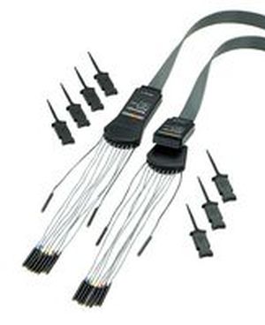
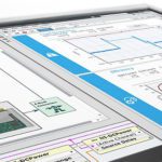
The buttons that access digital functions in the Tektronix MDO3000 Series oscilloscope are grouped together near the bottom of the front panel, just above the analog ports and the Analog Channel One input. Nearby is an insulated cover over the digital input ports and the digital D15-0 button.
You may wonder how it is possible to have so many inputs while the addition of only one or two analog inputs adds significantly to the cost of the instrument. The answer is that these signals are already digitized, and there is no need of ADCs with clocks and all they entail. The digital signals are applied directly to the main processor in the heart of the oscilloscope.
People who work in the analog domain generally hold the belief that digital signal processing and interpretation are substantially more mysterious and difficult to understand compared to analog signaling. Digital workers think the reverse. In reality, they are equally doable although different approaches are required.
Prior to undertaking a digital project, it is a good idea to look at the signals in the analog domain, as physical waveforms. It is here you can better see distortion and amplitude anomalies. They may be caused by simple hardware or cable routing flaws that can be corrected to prevent problems relating to digital decision thresholds.
In traditional electrical work, the term bus denotes a conductor, usually large and carrying lots of current. Typically, it is found inside switchgear and heavy electrical enclosures. Often these buses are rectangular and uninsulated, all the better to dissipate heat.
Bus has a different though related meaning in digital electronics. It refers not only to the conductor(s), which are smaller diameter and carry far less current, but also to the terminations at either end, any input and output modules and the protocol governing the assembly. The digital buses are:
• Audio
• CAN
• LIN
• FlexRay
• I2C
• SPI
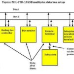
• MIL-STD-1553
• Parallel
• RS-232, RS-422 and RS-485
• UART
• USB
To use serial bus triggering, in the bus section on the front panel, press B1 or b2 and enter the parameters of the desired bus. Different buses can be assigned separately to B1 and B2. Go over to the right side of the front panel and press the Trigger menu button. The horizontal Trigger menu appears below the display. The various bus types require unique application modules, which can be purchased at the Tektronix website. They are available for free trial.
With the appropriate application module installed, you can use the oscilloscope to trigger on multiple digital buses. You can trigger on a parallel bus without an application module. After defining the bus using the B1 and B2 buttons and activating the trigger menu, begin by pressing the soft key associated with Type. The vertical Trigger Type submenu appears and Multipurpose Knob a can be used to select the type. The choices are:
• Edge
• Sequence
• Pulse Width
• Runt
• Logic
• Timeout
• Setup and Hold
• Rise/Fall Time
Each selection modifies the horizontal trigger menu as needed to suit the context. The second menu selection in the horizontal triggering menu is Source. Pressing the associated soft key, the vertical submenu lists the choices, which can be selected by turning Multipurpose Knob a.
One bus type, which is widely used, for example, is CAN bus. It may be selected from the vertical bus menu. You can trigger on:
• Start of Frame
• Type of Frame
• Identifier
• Data
• Id and Data
• End of Frame
• Missing ACK
If you are setting up a CAN trigger and have made a Trigger On selection of Frame Type, press Frame Type on the horizontal menu and choose Data Frame, Remote Frame, Error Frame or Overload Frame. If you have made a Trigger On selection of Identifier, press Identifier in the horizontal menu and choose a format. Then press Identifier on the side menu and enter a binary or hex value using Multipurpose Knobs a and b. Press Direction on the lower menu and choose either Read, Write, or Read or Write.
If you have made a Trigger On selection of Identifier, Data or Identifier and Data, press Identifier or Data on the horizontal menu and choose the parameters of interest on the vertical menu that appears.
You can trigger for a specific byte in CAN. Triggering takes place when your selected data input coincides with the data and qualifier in the signal beginning at the first byte. Define the number of bytes to match the number of bytes being examined. Use the data qualifier to perform operations that are exactly equal, less than, greater than, greater than or equal, or less than or equal. Triggering on Identifier and Data matches the identifier and data that you select, beginning at the first byte. A rolling window is not used.
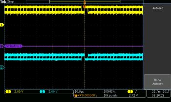
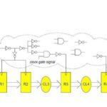
In Channel Two, label the signal Clock. As in Channel One, adjust the knob below the Channel Two button to reduce the signal height so it occupies less than half the screen. Press B1 in the vertical column of buttons to the right of the screen. Select Define Inputs and then use Multipurpose Knob a to assign Data to Channel One and Clock to Channel Two. Set both thresholds at one volt. Set Bus Display to Bus and Waveform and choose Hex. Press the Trigger Menu button, select Bus, Source B1 I2C and Trigger on Start. Turn the Scale knob to set the scale at one ms. Press Single to display one waveform.
The chief difference between parallel and serial bus protocols is that in parallel communications, multiple bits transfer simultaneously whereas in serial communication, one bit at a time transfers. In a typical parallel bus, there are eight conductors, D0 through D7, while in a serial bus there is one conductor, named D0 at the transmitter and D1 at the receiver, in both cases not counting the essentially non-current-carrying ground. It is not correct, however, to assume that parallel communication is necessarily faster, because clock speed and slew in addition to other issues are relevant.
Within hardware, parallel data links make sense because the distances are short and design mandates constrained. Serial communication requires additional processing since it must revert to parallel form by means of a universal asynchronous receiver-transmitter (UART) prior to reconnection to a data bus.
Serial communication is characterized by the transmission of single data bits in succession. It has largely replaced the older parallel communication, in which multiple conductors convey a relatively large number of data bits simultaneously.
Serial communication is more practical in long-haul links as well as in most computer networks where greater cable costs and synchronization challenges make parallel communication less feasible. Even at relatively short distances, serial communication is becoming more common, due to better signal integrity and higher transmission speeds. While parallel bus is conceptually simpler, it is prone to clock skew and interconnect density. Parallel communication is easier to understand but more difficult to implement.

Leave a Reply
You must be logged in to post a comment.