
At DesignCon 2019, I met with Todd Westerhoff, HyperLynx high-speed design analysis product manager at Mentor, a Siemens Business. Todd has over 38 years of experience in systems modeling, simulation and signal integrity. Prior to joining Mentor, Todd held senior technical and management roles at SiSoft, Cisco and Cadence. We spent time talking about current trends in high-speed design and why signal integrity is needed for most designs today.
At Mentor, you’re focused on signal integrity (SI). Tell me why this is a critical area right now.
Today’s devices have reached speeds where literally every signal in a PCB behaves as a transmission line, susceptible to problems with reflection and ringing. It’s not necessarily a data rate problem, it’s an edge rate problem. If a 100 kb/s I2C bus has a ringing problem, it can be enough to bring down the whole system. It’s usually impractical to perform signal integrity simulations for every net on a board, so designers follow best design practice guidelines to manage SI issues, reserving SI simulation for nets considered as highest risk.
Best practice guidelines simplify the design process, but they can also increase product cost or lower performance. Each product has a unique set of targets for performance, risk, cost, and development schedule. To truly optimize a design, designers need to understand details of component timing, signal propagation and the system’s Power Delivery Network (PDN). The most effective engineers have a solid grasp on SI/PI principles and the use of simulation tools to explore design tradeoffs.
Why aren’t more designers using SI analysis tools? Do mainstream PCB designers feel it’s something that should be left for SI experts to manage?
Unfortunately, most PCB designs don’t get simulated before fabrication. There are several common reasons for this:
- Lack of accurate models in time
- Lack of SI tools or expertise
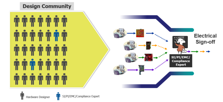
- Limited access to SI “experts”
The last reason is becoming more common – SI, PI and EMC are seen as specialized skills to be performed by seasoned experts. The problem is, there are never enough experts to go around, so design problems not considered “bleeding edge” have to go without SI/PI support. Simple problems can go undetected until late in the design cycle, where they can require significant rework and associated delay.
In practice, most problems aren’t associated with “bleeding edge” signals, and don’t require detailed simulation to identify and resolve. Automated design rule checking (DRC) can find a wide assortment of SI, PI, EMC and safety compliance problems in real-time during layout, allowing immediate correction. This technique doesn’t need SI models at all.
We’ve also been experimenting with using generic SI simulation models to evaluate basic design trade-offs through simulation. Generic models represent a technology like DDR4 and are not specific to a device or manufacturer. We’ve found this technique to be surprisingly effective, allowing design work to proceed where it would otherwise be stopped for lack of models.
I’ve heard “power-aware” simulation mentioned in the context of ensuring design reliability and robustness. Can you elaborate?
Power-aware simulation considers interactions between a system’s high-speed signals and Power Delivery Network (PDN) that other simulation techniques neglect. These interactions are unwanted, unavoidable and only serve to reduce voltage and timing margins. HyperLynx power-aware simulation lets designers evaluate different mitigation strategies to determine their effectiveness and identify the most cost-effective solution. This is particularly interesting for high-volume, low-cost designs which are always layer and space constrained – since power-aware simulation delivers a quantitative way to make design trade-offs.
What about design certification and compliance? How are you advancing your tools so customers can test and analyze their designs with high confidence?
We believe automating design compliance testing is essential to minimizing certification risks. According to Lifecycle Insights, 78% of all projects experience two or re-spins. Design compliance analysis is often based on visual reviews by experts and peers. Manual review is imperfect, errors can go undetected until lab testing or make it to the released product. Clearly, such errors can have a big impact on schedules, design quality and profitability.
Mentor’s verification and simulation tools are integrated with the Xpedition PCB design flow to provide checking at each stage of the design process, with the intent of allowing errors to be identified and corrected at the point of introduction. We refer to this as “shift-left” design, since it brings analysis forward in the design cycle, helping reduce cycle times and improve overall product quality.
More resources about signal integrity including papers, videos, and virtual labs, as well as Mentor’s Hyperlynx product can be found at www.mentor.com/hyperlynx


Leave a Reply
You must be logged in to post a comment.