Engineers whose test bench already comes equipped with power supplies, meters, and electronic loads might wonder what good a source measure unit might be. Here’s the rationale for this type of instrument.
Qing D. Starks • Tektronix Inc.
Most engineers have a power supply and a DMM on their benches. So it’s logical to ask why a source measure unit (SMU) instrument that incorporates both would add value and increase productivity. It turns out that combining a power supply, DMM, current source and electronic load creates a test instrument that for many applications is more versatile than the individual instruments are alone.
There are a few differences between an SMU and its forefathers, the DMM and the power supply. In a general sense, the SMU can be either a voltage source (with a programmable current limit) or a current source (with a programmable voltage limit). Both the source and limit functions can be programmed with 16-bit resolution, and both quantities can be measured with the precision of a high-resolution DMM. Comparing the SMU’s finer points with those of the more familiar power supply or DMM may help clarify the differences.
Speed – Many power supplies are designed to limit currents that are effectively dc, but SMUs typically do so with much higher bandwidth. The speed of the source and limit function depends on load. But in some cases, SMUs can source or limit to a settled current or voltage value in as little as 50 msec. What’s more, the limiting is fast enough to protect components and entire circuits from over-current conditions—not true for low-cost power supplies. SMUs also let you apply voltage or current in pulses to limit device power.
Dynamic range – Most power supplies only have a few ranges, and many have only one. Depending on the model, the large dynamic range of an SMU permits measuring currents from as low as a few hundred femtoamps all the way up to 50 A. The lower current ranges are useful for component characterization, finding components that are slightly damaged, and debugging super-low-power applications.
High resolution – Like DMMs, SMUs offer high resolution and up to 22-bit measurement functions for both voltage and current.
Programmability – SMUs can be programmed to pulse their voltage or current or to program any special sequence of voltage or current. For higher-end SMUs, the built-in programming language is powerful enough to define waveforms in the manner of an arbitrary waveform generator (ARB) that can source both voltage and current.
Input impedance – Unlike DMMs, SMUs maintain high input impedance up to the voltage capability of the instrument. In contrast, DMMs (and oscilloscopes) use resistive dividers to measure high voltages.

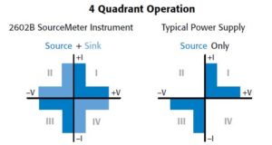
Four-quadrant operation – SMUs can source positive and negative current at either positive or negative output voltage. Thus the output amplifier covers all four source quadrants, and it can be used as an electronic load. A typical power supply can only source voltage and/or current, thus providing only two-quadrant operation. During operation as a source or sink, the SMU can simultaneously measure voltage, current, and resistance. This operating flexibility can be especially valuable when characterizing batteries, solar cells, or other energy generating devices.
SMU scenarios
A few scenarios help illustrate where SMUs can come in handy. In one, suppose we’re working on a new power supply design on a tight deadline with specifications changing at the last minute. It’s a feature-rich, software-controlled power supply with numerous operating modes for different applications. Among the power supply features are programmable supply voltage, step response, and high efficiency. It employs power factor correction (PFC) and an off-line (mains) supply followed by several push-pull forward converters with lots of secondary outputs. Further suppose the supply has many other software-controlled features, not all of which are finished. A major concern is that software mistakes could damage the board.
Before sending the boards off for fabrication, we take one to the test bench. Using an SMU, we apply the rated supply output voltage to each of the output supply printed circuit board traces (PCBT), as well as to the line (mains) voltage circuits. When the supply is running, it must operate at the rated voltages, so why not try them out with a safe 10 μA current limit first?

The line voltage (and safety spacing) looks okay, as do all the low-voltage supplies. But the 700-V high-voltage output hits the 10 μA current limit immediately. Something is very wrong. The SMU reports the limit voltage at 350 V, a clear indicator of a voltage breakdown issue rather than a short. And in fact, the breakdown occurs at 350 V.
After some digging, we discover that milling a slot between the high-voltage net (high-voltage traces on the PCB) and a short ground track on the PCB solves the problem. It turns out that voltage spacing rules for this net were never enforced by the computer-aided design (CAD) tool. The engineer maintained spacing as he ran the traces but must have forgotten one. Finding this mistake early let the slot be added before the boards were populated. It would have been much more difficult to correct the breakdown problem after the board had been populated.
With this problem solved, suppose we grab a new board and set the SMU to provide line voltage by executing an ac line voltage test script we’ve written. The script programs the output to a 50-Hz sinusoid with the correct limit current for the quiescent current of the unloaded supply.
The new board powers up fine with all supply voltages within specifications. Using an oscilloscope, we look at the voltage across each rectifier to capture an entire power supply switching cycle. This change in voltage across the rectifier diode reflects the load current defined by the log amp I/V curve that can be found with an SMU. If these traces do not look like a simple shift, or if the shift is not correct, there may be a problem in the secondary circuits following the rectifier.
Suppose the voltage on each rectifier of each output looks correct. If the rectifier current was too high for any reason, the rectifier voltage (essentially a log amp), would have shown this increase in current over time. We can use a second SMU to measure the I-V characteristics of each diode and find what the voltages should be. The procedure is one of programming the SMU to apply a sweeping voltage and measuring current.
Further suppose problems surface: Within about 30 minutes the SMU powering the second board reaches its current limit. This time, however, nothing fails and the board doesn’t burn up. We simply had to turn off the output of the SMU to program the instrument to zero volts and restart the ac line voltage script.

To isolate the problem, we use an oscilloscope to measure the primary currents of each push-pull supply. There are typically no resistors in these lines, but we may measure the primary current by measuring the small voltage drop across a one-inch PCB trace. While this test normally takes place with a floating oscilloscope, we can also use a high-resolution digitizing DMM.
This measurement proves enlightening. In just a few minutes, we notice that the magnitude of the current was rising! Because the previous tests showed that the secondaries were fine, that left one of two possible problems: Either the transformer was incorrectly designed or manufactured or the push-pull ON time for each of the half cycles of the push-pull MOSFETs were unequal, a condition known as flux imbalance.
After much sleuthing, we discover that the problem was in the controller code for the MOSFET switching. Apparently, an interrupt executing only during half of the push-pull sequence, and which always took place on the same switch, was changing the ON time enough to cause a flux imbalance problem in the transformer. Our transformer design was particularly sensitive to this issue because this design had little magnetizing inductance. On this project, the SMU played a key role in debugging a serious problem.
Power consumption testing
Moving to a different scenario, consider the task of validating and debugging an advanced energy harvesting watch for military applications. It has wireless capabilities for tracking soldiers and keeping the wearer in touch with central command. It also syncs time and date with other watches in the command. Sometimes it passes key information to soldiers by passive LCD, sometimes by flashing lights, and sometimes by a mild electric shock. It scavenges power from body heat, light, and movements. And it has dozens of operating modes, each consuming a different quiescent current.

Test setup with fixture for the example of an SMU testing a military energy harvesting watch.
A critical concern is keeping watch current consumption under the magic threshold of 1 nA, the lowest guaranteed current delivered by the watch’s combined energy harvesting techniques. If the watch current ever exceeds 1 nA for any amount of time, the watch must reduce its load for a period to “make up” for the extra energy drain.
Initially, we test each of the peripherals with an SMU and a low-leakage guarded test fixture. SMUs, such as the Keithley Model 2461 SourceMeter instrument, are available with the necessary low current measurement ranges and low-noise-current triaxial cable connectors.
This setup allowed us to record not only the current consumption but also the rate-of-change of the current when enabling or disabling the candidate circuits. Slight changes had a measurable impact. For instance, changing the current consumption too quickly forced the energy harvesters to operate at a lower efficiency. We used the SMU to simulate the I-V characteristics of the watch solar cells to test the watch’s ultra-high-efficiency power converters. This testing required a fast source capable of operating at high voltages as well as low currents.
We then moved to the test fixture. The watch housing and wrist strap were unavailable, so the test fixture and triaxial cabling had to be used to guarantee measurements of current consumption were valid. Surrounding the device with a Faraday shield ensured that all measured current would be from the watch itself and not caused any spurious external influences.
The fixture also let engineers and auditors operate the watch using their computers, rather than using the watch buttons. This interface was developed to speed the audit and let it take place anywhere.
To speed the test procedure, we wrote code to run on the SMU that made the instrument continuously monitor the watch load current as the SMU supplied power. The code let the instrument track all instances over the 1-nA limit as well as the average current.
A misbehaving feature could cause an audit to fail. It could also fail if the watch were to consume excessive current. Whenever this happened, engineers would inspect the specific hardware state causing the failure—and find a solution.
Given the complexity of the design, the audits were somewhat unpredictable. The team had to repair instances of excessive current consumption and feature implementations that were broken. However, SMUs reduced debugging time compared to that necessary when using separate power supplies and electronic loads lacking low-current performance and programmability.
In a nutshell, an SMU can help save time solving problems while reducing repair and rework. To be sure, the degree of usefulness that a measurement tool provides is directly related to your understanding of its functions and how to use them to their fullest.

Leave a Reply
You must be logged in to post a comment.