• Skip to primary navigation
  • Skip to main content
  • Skip to primary sidebar
  • Skip to footer
  • Advertise
  • Subscribe

Test & Measurement Tips

Oscilloscopes, electronics engineering industry news, how-to EE articles and electronics resources

  • Oscilloscopes
    • Analog Oscilloscope
    • Digital Oscilloscope
    • Handheld Oscilloscope
    • Mixed-signal Oscilloscope
    • PC-based Oscilloscopes – PCO
  • Design
  • Calibration
  • Meters & Testers
  • Test Equipment
  • Learn
    • eBooks/Tech Tips
    • FAQs
    • EE Training Days
    • Learning Center
    • Tech Toolboxes
    • Webinars & Digital Events
  • Video
    • EE Videos
    • Teardown Videos
  • Resources
    • Design Guide Library
    • Digital Issues
    • Engineering Diversity & Inclusion
    • Leap Awards
    • White Papers
  • Subscribe
You are here: Home / New Articles / Sorting out balanced cables and differential signaling

Sorting out balanced cables and differential signaling

August 26, 2022 By David Herres Leave a Comment

Lines carrying symmetric signals, i.e. those with opposite polarities but with equal amplitudes on each line are commonly called balanced. But the correct term is differential signaling. While balanced lines and differential signaling may be used together, they are actually quite different.

balanced lines and differential
Audiosciencereview.com put together a graphic that illustrates the difference between balanced lines and differential connections. Click image to enlarge
The key point that distinguished balanced lines from single-ended lines is that both of the balanced lines have the same impedance to ground. Because the lines have the same impedance to ground, interfering fields or currents induce the same voltage in both wires. This lets a differential amplifier reject the resulting common-mode interference. If the cable containing the balanced line conductors includes a shield connection, the shield is not part of the main signal path.

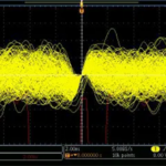
One potentially confusing factor is that balanced lines generally take the from of twisted pairs–but twisted pairs are not necessarily balanced lines. Intentionally twisting individual data-carrying pairs greatly increases immunity to electromagnetic interference and crosstalk. The reasoning behind this mitigation technology is that twisting one or both conductors keeps them in close proximity to one another. Because electrical current in the two wires is going in opposite directions, they will create magnetic fields that are equal and opposite to each other. The result is a cancellation of EM radiation from the wire. Moreover, EM radiation coming from external sources will affect each wire equally due to their close proximity. The induced noise and crosstalk are common-mode signals that can be attenuated if not completely canceled through use of a differential receiver (or a transformer).

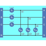
Another confusing bit: Balanced lines can be used with both differential amplifiers and with single-ended amplifiers. Differential signaling involves the two balanced-line conductors (with an optional shield) carrying the same signal at opposite polarity. More specifically, look at the voltage on each of the two lines and you will see two waveforms that are mirror images of each other. That is, when voltage on one line is at a maximum, voltage on the other line is at a minimum. The signals are not necessarily oscillating around zero; they can be at any voltage. The only requirement for understanding the effect is that the two are mirror images. Whatever is different between the two wires is what is amplified by the differential amplifier.

The same result can be obtained using single-ended amplifiers and balanced lines. Here the signal is often coupled into the balanced line and extracted at the other end via a transformer to ground, or via equivalent circuitry. The result is generally a somewhat more distorted signal than would be the case with differential amplifiers. But noise is rejected in both the differential amplifier and single-ended amplifier case.

cross over on a telephone pole
An early form of twisted-pair: Crossing wires implemented on a telephone pole.
It was early telephone engineers who probably first implemented this technique. They installed single-conductor (with ground-return) voice lines on telegraph poles. In the lower-noise environment of the day, they simply crossed the conductors at every other pole. But soon ever-increasing EMI resulting from proliferating powerlines overwhelmed the cross-over technology.

When nearby pairs have equal twist rates (here we are talking about a conduit installation, metal or PVC), the proximity of different conductors within pairs remains constant, defeating the design goal. Here again a simple solution is available: altering the twist rate just a slight amount so as to disrupt the otherwise high degree of capacitive coupling.

A disadvantage in twisted pair because of different twist rates is that in video applications the varying amounts of skew will severely impact quality. Low-skew cable is a good solution.

Now consider single-ended signaling via a single conductor and ground instead of via a balanced line. Even if the signal and ground wires are twisted together, there can be common-mode noise. Moreover, any other noise (perhaps leaking in through the ground connection) will look like a signal to the receiver.

You may also like:


  • The difference between electronic distortion and noise
  • pico technology
    Applying PC-based test & measurement instruments

  • Scope-based diagnosis of three-phase motor drives
  • DACs
    The ups and downs of bad DACs

Filed Under: FAQ, Featured, New Articles, Test Equipment Tagged With: FAQ

Reader Interactions

Leave a Reply Cancel reply

You must be logged in to post a comment.

Primary Sidebar

Featured Contributions

Why engineers need IC ESD and TLP data

Verify, test, and troubleshoot 5G Wi-Fi FWA gateways

How to build and manage a top-notch test team

How to use remote sensing for DC programmable power supplies

The factors of accurate measurements

More Featured Contributions

EE TECH TOOLBOX

“ee
Tech Toolbox: 5G Technology
This Tech Toolbox covers the basics of 5G technology plus a story about how engineers designed and built a prototype DSL router mostly from old cellphone parts. Download this first 5G/wired/wireless communications Tech Toolbox to learn more!

EE TRAINING CENTER

EE Learning Center

EE ENGINEERING TRAINING DAYS

engineering
“test
EXPAND YOUR KNOWLEDGE AND STAY CONNECTED
Get the latest info on technologies, tools and strategies for EE professionals.
“bills

RSS Current EDABoard.com discussions

  • Identification of a 6 pin smd chip (sto-23-6) marked E2
  • Dynacord enter protect
  • IGBTs without negative gate drive
  • Need suggestions in task NI6363 retrigger (analog trigger)
  • Monte-Carlo simulation error on ADE-XL

RSS Current Electro-Tech-Online.com Discussions

  • Does US electric code allow branching ?
  • Faulty heat air gun (dc motor) - problem to locate fault due to Intermittent fault
  • Fun with AI and swordfish basic
  • Sump pit water alarm - Kicad 9
  • turbo jet fan - feedback appreciated.
Search Millions of Parts from Thousands of Suppliers.

Search Now!
design fast globle

Footer

EE World Online Network

  • 5G Technology World
  • EE World Online
  • Engineers Garage
  • Analog IC Tips
  • Battery Power Tips
  • Connector Tips
  • DesignFast
  • EDA Board Forums
  • Electro Tech Online Forums
  • EV Engineering
  • Microcontroller Tips
  • Power Electronic Tips
  • Sensor Tips

Test & Measurement Tips

  • Subscribe to our newsletter
  • Advertise with us
  • Contact us
  • About us

Copyright © 2025 · WTWH Media LLC and its licensors. All rights reserved.
The material on this site may not be reproduced, distributed, transmitted, cached or otherwise used, except with the prior written permission of WTWH Media.

Privacy Policy