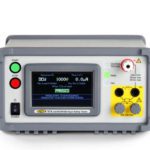
A few simple steps ensure testing takes place safely when potentially lethal voltages and currents are involved in the testing process. Kevin Clark, Vitrek Inc. Hipot testing has long been a standard procedure for assuring the electrical safety compliance of electronic equipment. Early commercial hipot testers were actually not much more than a variac-driven step-up […]
FAQ
Understanding and testing asynchronous logic
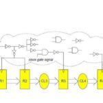
Traditionally, computer and instrumentation engineers work with synchronous logic, where a global clock circuit imposes a timing structure to which all circuits down to the components level adhere. In synchronous logic, an autonomous oscillator outputs a square wave that never varies in frequency or amplitude. At the rising edge (sometimes falling edge) a potentially vast […]
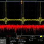
The difference between MDO and MSO displays with time domain and Fast Fourier Transforms
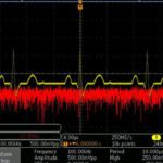
Mixed-domain oscilloscopes and mixed-signal oscilloscopes differ significantly in how they display waveforms. Both are useful because they permit users to simultaneously view different electrical aspects of equipment under investigation. The MDO displays a single signal simultaneously in the time and frequency domains, demonstrating how they change together. The MSO displays two different signals in the […]
Working with optical fiber
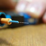
Optical fiber is actually a waveguide for light and operates in accordance with a principle known as total internal reflection. In contrast to electrical conduction, there is low loss and signals can be conveyed over considerable distances without amplification. Total internal reflection happens when a propagated wave strikes the boundary between two dissimilar materials, provided […]
Basics of active and differential scope probes
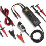
By far the most used oscilloscope probes are the passive 10:1 attenuation probe. It is appropriate when the frequency of the signal under investigation is less than 600 MHz. Impedance matching from the probe tip to channel input port is critical. A mismatch gives rise to reflections, collisions and loss of data. At dc to […]
Working with the PicoScope PC-based oscilloscope
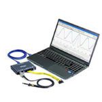
A PC-based oscilloscope, or USB oscilloscope as it is also known, has a lot going for it. For one thing, it costs substantially less than a bench model with equivalent specifications, given that most users already own the major component. The PC or Mac provides the processing and display parts of the equation. (The computer, […]
Working with waveforms in mixed-domain oscilloscopes
Waveform generators generally contain a library of common waveforms, which can be individually accessed and displayed by running a BNC cable to an active analog channel input in an oscilloscope. Most oscilloscopes have, available as an option, an internal arbitrary function generator (AFG), which permits the user to create an endless variety of waveforms and […]
Digital phosphor oscilloscopes, persistence, and eye patterns

The digital phosphor oscilloscope takes its name from the old analog phosphor scope, but the resemblance is superficial. It was difficult to see the trace on the CRT screen in an analog scope because the electron beam dissipated instantly. To solve this problem, early engineers came up with the idea of coating the inner surface […]
The basics of simulating radar signals with AWGs
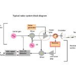
Radar is quite simple in concept, but it becomes highly complex in actual implementation. Many decades passed between the time it was first envisioned and when useful working models emerged, which happened just in time to save England from total defeat in the 1940s. When it comes to testing radar, the situation has become easier […]
A test setup that simulates automotive radar
Jungik Suh from Keysight recently took us through a simulation of an automotive radar system, a hot topic these days thanks to work being done in autonomous vehicles. The point of simulating a radar signal is to provide a test signal for downstream electronics that will act on what shows up in the radar return. […]
