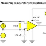
A comparator, as its name suggests, compares two voltages or currents and determines which is higher. The usual implementation is with two inputs for the voltages that are to be compared and a single output that by mean of a logic high or logic low state indicates the higher of the two inputs. Typically, a […]
FAQ
Measuring pulse-width modulation outputs in industrial equipment
Pulse-width modulation (PWM) is a widely used means of controlling power to large induction motors by means of variable-frequency drives (VFDs). The VFD is capable of varying the speed and torque of an otherwise single-speed ac motor, typically a three-phase 480-V induction motor. Typically housed in a floor-to-ceiling steel enclosure, the VFD modifies the power […]
Measuring polarization
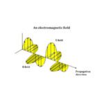
Any treatment of wave polarization must begin with a discussion of the differences between transverse and longitudinal waves. That is because polarization either as a process or a state applies only to transverse waves, not to longitudinal waves. Longitudinal waves are those in which the oscillations are in the direction of propagation. Examples of longitudinal […]
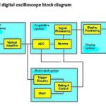
Understanding sampling modes in digital oscilloscopes
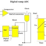
In a digital oscilloscope, the analog signal is at the input, after attenuation/amplification and preliminary filtering such as for ac coupling, goes to an analog-to-digital converter (ADC). Each channel has a separate ADC, each with an external clock. Analog-to-digital conversion takes place by means of sampling. The samples are taken at specific rates and the […]
Logic analyzer basics: The difference between a scope and a logic analyzer
The logic analyzer is an advanced instrument that displays the content of numerous digital data streams simultaneously and in various formats. It is continuously evolving. Manufacturers are offering new and ever more advanced features that facilitate with great precision design, debugging and repair of digital systems. While the oscilloscope remains relevant in the digital domain, […]
Basics of testing CMOS

The term complementary metal-oxide semiconductor (CMOS) has become a partial misnomer because the dielectric layer that separates gate and source is now rarely a metal oxide. The name persists despite this change. CMOS refers to pairs of MOSFETs in symmetrical configurations, which in turn are slightly modified FETs. CMOS circuits have become by far the […]
Characterizing digital logic signals with an oscilloscope

Transistor-transistor logic (TTL) and complementary metal oxide semiconductor (CMOS) logic are the principal types of integrated circuit-based logic gates implemented in digital circuitry. TTL employs bipolar junction transistor technology while CMOS uses the field-effect transistor concept at the input. TTL consumes far more power than CMOS, which is one reason CMOS has eclipsed TTL as […]
Making best use of acquisition memory in digital storage oscilloscopes
A typical computer contains at least two separate memory substructures: random-access memory (RAM) and read-only memory (ROM). The digital storage oscilloscope (DSO) also has two types of memory: acquisition and display memory, but beyond that the comparison is tenuous. In talking about a DSO, memory generally refers to acquisition memory. The highly complex interaction between […]
The basics of digital oscilloscope acquisition controls
Digital oscilloscopes are characterized by an acquisition menu, permitting the user to choose among modes and to select the record length, horizontal position and waveform, and to turn on or off Fast Acq, Delay and XY Display. We’ll look at each of these in turn. The essence of digitalization is that points comprising a waveform […]
Precision and accuracy in oscilloscopes
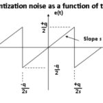
The precision and accuracy of voltage measurements made with a digital scope are affected by the speed at which samples are taken, i.e. the sampling rate, and sampling depth or bit depth. Bit depth is just the number of bits of information in each sample, and it directly corresponds to the resolution of each sample. […]
