Microphones are familiar sensors that transform sound pressure waves into electrical signals over a broad range of frequencies and amplitudes. They are an integral part of a variety of devices including tape recorders, hearing aids, telephones, and computers. They are also used in radio and television broadcasting and audio engineering. But another specific class, perhaps not as well known, is intended for the scientific measurement of certain types of sounds and noise levels, including ultrasound. Sounds monitored for test and measurement purposes are recorded, analyzed, and typically assigned somewhat different quantitative and qualitative values than voice and music in the entertainment industry. The most common types of microphones include carbon, magnetic, piezoelectric, and condenser.
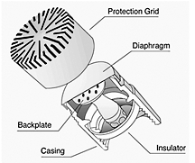
Each type is best suited for a specific application. For example, carbon microphones were first used in telephones and for radio communications. They are relatively low-cost, rugged, two-terminal devices that contain a small cartridge of lightly packed carbon granules, usually biased with current or voltage. When acoustical pressure waves hit the microphone, the carbon granules compact and relax thus modulating the terminal resistance. The continuously changing resistance then generates an output signal of varying voltage or current in step with the sound pressure waves at the microphone’s input.
Magnetic microphones are dynamic transducers that contain a moving coil, and are based on the principal of magnetic induction. Here, a coil of wire attaches to a lightweight diaphragm, which is in the presence of a magnetic field. The coil moves and generates a voltage proportional to the applied acoustical pressure.
The third type, a piezoelectric microphone, uses either a natural quartz or manmade ceramic crystal. Although these microphones have relatively low sensitivity levels, they are durable and can measure high amplitude pressures. Conversely, their noise-floor level is generally high, which make them particularly suitable for shock and explosive-type pressure measurements.
Condenser microphones come in two types, externally polarized, and pre-polarized. They transform the sound pressure waves into capacitance variations, which are then converted to electrical signals. The unit’s cartridge comprises a small thin diaphragm spatially in parallel with, but not electrically contacting a stationary metal back plate connected to a voltage source. In the presence of oscillating pressure, the diaphragm moves and changes the gap between the diaphragm and the back plate. This produces an oscillating voltage output, which is proportional to the original pressure signal.

The voltage source for an externally powered condenser microphone is usually a 48 to 200 V power supply. By comparison, a newer pre-polarized microphone has an “electret” layer of charged particles deposited on its backplane to supply the polarization. The electret microphone can use inexpensive constant-current supplies instead of costly polarized power supplies. Also, more economical BNC coaxial cables or 10-32 connectors can be used instead of the LEMO-type, 7-pin connectors and cables. Coaxial cables can carry the signals over long distances without significant degradation. Modern pre-polarized microphones are becoming the preferred type for laboratory test, measurement, and field applications.
Selecting and specifying microphones
Most types of microphones can measure broadband sound pressure levels from a variety of sources, but high-precision condenser microphones characterize the sound better than most. When choosing the optimum microphone, a number of factors must be considered: the application, the sound source, and the operating environment. Also, investigate the type of response (application) field, dynamic response, frequency response, polarization type, sensitivity required, and temperature range needed. A variety of condenser microphones are available for specific applications.
Precision condenser microphones work well in three common application fields: free-field, pressure-field, and random-incident (diffuse) field. Free-field microphones are intended for measuring sound pressure variations that radiate freely through a continuous medium, such as air, from a single source without any interference. The microphone is typically pointed directly at the sound source (0º incidence angle). Free-field microphones measure the sound pressure at the diaphragm; however, the sound pressure may be altered from the true value when the wavelength of a particular frequency approaches the dimensions of the microphone. Consequently, correction factors are usually added to the microphone’s calibration curves to compensate for any changes in pressure at its diaphragm due to its own presence in the pressure field. These microphones work best in anechoic chambers or large open areas where hard or reflective surfaces are absent.
The second type is called a pressure-field microphone. They measure sounds from a single source within a pressure field that has the same magnitude and phase at any location. In order to simulate a uniform pressure field, they are usually calibrated in enclosures or cavities, which are small compared to their wavelength. This minimizes any alterations in measurements due to the presence of the microphone in the sound field. They are also supplied with a pressure versus frequency-response curve. Such microphones measure the pressure exerted on walls, airplane wings, or inside structures such as tubes, housings, and cavities.
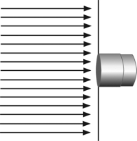
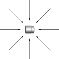
The third type is called a random-incident or a diffuse-field microphone. They are omni-directional and measure sound pressure from multiple directions and sources, including reflections. They come with typical frequency response curves for different angles of incidence and compensate for the effect of their own presence in the field. An appropriate application for this type of microphone is measuring sound in a building with hard, reflective walls, such as a church.
Dynamic response
The main criterion that describes sound is based upon the amplitude of sound-pressure fluctuations. The lowest amplitude that a healthy human ear can detect is 20 millionths of a Pascal (20µPa). Since the pressure numbers represented by Pascals are generally extremely small and not easily managed, another scale is more commonly used, called the decibel (dB). This scale is logarithmic and more closely matches the response of the human ear to pressure fluctuations. Some examples of typical sound pressure levels used as a reference include the following:
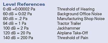
Typically, the maximum decibel level is based on the physical characteristics of the condenser microphone. The specified maximum dB level refers to the point where the diaphragm approaches the back plate, or where total harmonic distortion (THD) reaches a specified amount, about 3% or less. The maximum level in dB that a microphone outputs in a certain application depends on the voltage supplied and its sensitivity. In order to calculate the maximum output for a microphone, use a specific preamplifier and its corresponding peak voltage, and then calculate the pressure in Pascals that the microphone can accept. The amount of pressure is determined from the following equation:
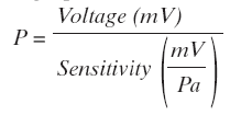
Where: P = Pascals, Pa
Voltage = the preamps output peak voltage, V.
After the maximum pressure level that the microphone can sense at its peak voltage is determined, it can then be converted to dB using the following logarithmic scale:
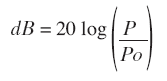
Where: P = Pressure in Pascals, Pa
Po = Reference Pascals, Pa (Constant = 0.00002 Pa)
The microphone’s cartridge thermal noise (CTN) rating indicates the lowest measurable sound pressure level that it can detect above the electrical noise inherent within the microphone. The inherent noise level of a microphone and preamplifier combination is highest at both the lower and upper limits of the microphone. Each microphone has a unique noise characteristic, and the diameter of the microphone strongly influences its frequency response and noise level.
Frequency response
After the microphone’s field response and dynamic range have been determined, find the usable frequency range from its specification sheet. Proper selection requires that the measured pressure levels fall between the microphone’s low-end noise level (CTN), and the maximum rated dB level of the microphone. In general, the smaller the microphone diameter, the greater the high-end dB level expected. The larger diameter microphones are recommended for lower frequency range amplitude (dB) measurements since the inherent noise or CTN specifications are typically lower.
Manufacturers typically specify a ± 2 dB tolerance on the frequency versus output amplitude. When comparing microphones, check the tolerance in the specific frequency range most needed. When an application is not critical, select a wider frequency range with a higher allowable output (dB) tolerance from the manufacturer’s specification sheet.
Polarization type
Condenser microphones are further classified in two categories; traditional externally polarized and pre-polarized microphones. Either type works well for most applications, but the pre-polarized units tend to produce more repeatable output in humid surroundings. Pre-polarized microphones are recommended where temperature changes can promote condensation and short circuits on the internal components of externally polarized microphones. Conversely, at temperatures between 120 and 150º C, externally polarized microphones are better suited, because their sensitivity level is more consistent in this range.
Microphone sensitivity is inversely proportional to temperature. Microphones operated or stored in high temperature environments may require calibration more frequently. However, a probe microphone is specifically intended for withstanding these kinds of harsh environments. It combines a microphone with a probe-type extension tube for mounting close to the sound source. The probe tip contains the microphone, and the signal-conditioning module may be remotely located, either in a less harsh environment or where access to the sound source is too small for a typical condenser microphone.
Special applications
Microphones are often designed for special applications. For example, corrosion-resistant microphones called hydrophones are used for testing, monitoring, and measuring sounds under water. Different models are available for different sensitivities, frequencies, dB levels, and operating depths.
Another particular type, sound level meters, are special instruments intended to read sound pressure levels quickly and conveniently. Portable units are usually small, handheld instruments, which include the microphone, preamplifier, power source, software, and display. They measure ambient noise levels on the street and artillery ranges; in factories, power generating plants, shopping malls, office buildings, and numerous other places.
Intensity probes are usually the best choice for measuring the magnitude and direction of a sound. The set up usually consists of two phase-matched microphones with a spacer between them. They measure the pressure level as well as the speed and direction of the propagating sound waves. The higher frequencies typically require a smaller spacer, while larger spacers are used for lower frequencies or where sounds might reverberate.
Array microphones are used for near-field, acoustic holography (NAH). These are applications where 3D field values are studied. A number of array microphones are placed in a predetermined pattern and combined with appropriate software to map the acoustic energy flow of a complex sound pressure field. Array microphones work especially well where a large number of microphones are used concurrently. Also, Transducer Electronic Data Sheet (TEDS) are recommended to be used with arrays, since they let the user quickly and easily identify a particular microphone within the array. TEDS chips and firmware are typically stored electronically in each microphone and list its model number, serial number, calibration date, along with the specifications of the microphones sensitivity, capacitance, impedance, and other information that can be downloaded to help ensure accurate test results.

Finally, outdoor microphones can withstand rigorous environmental exposure, such as in airports and on highways. Noise measurements here are crucial to providing information for improving human safety conditions. Environmental and outdoor microphones provide different levels of protection for the internal components, while maintaining their high-accuracy specifications.

Hi,
I am working on School project to build an acoustic dosimeter.
I bought some mics, and i need to test their specs if they are the same as per datasheet. The specs that i need to test is the below
1)Dynamic range: 80 decibels to 140 decibels (SPL)
2)Frequency response: 20 to 20,000 Hz
I need your help, can you guide me which equipements, can help me to test my the specs above and if i need to rent/buy some equipments/software from you to help me in my tests?
Also, I am looking to buy/rent any equipement/software that i can use to visualize the mic’s signal in dB or dBA(preferable)?
Thanks
Peter Rafla
contact information:
Name: Peter Rafla
Cell: 514-969-3931
address: 4020 st jean D.D.O.,Montreal, Quebec, Canada…(H9G 2L6) App.#402
School name: École Polytechnique de Montréal
Location: Montreal, Quebec, Canada…Code postal: H9G 2L6
School email: peter.rafla@polymtl.ca
I was looking for ways to find out of testing an unknown mic. I got a tiny mic, about 1/4in in diameter pulled out of a camcorder and I would like to hook it up but I am not sure how to find out the way what amp would take the signal from it and make the V change. Any suggestions?
Thanks much.
Hi,
I was looking for some information about microphone array. i want to know about the theory of their working and their application. can you help me or refer me to some refrences.
Best Regards
Ehsan Jabbari
how do i test my mic if it is in a good condition with a Multitester or Oscilloscope ? pls guide me how to do the test i use a local mic 54j4
what are the problems arise in the condenser microphone? Is there any problem will occur related to soldering the microphone?
Hi,
I’m trying to study the distortion by calculating the TDH of three condenser microphone. An electrect, a prepolarized class one and a prepolirized class two. The fact is that the lowest TDH is given by the prepolarized class two and I don’t understand why. Can anybody explain me that?