We recently talked with Greg Jue from Keysight who took us through a demo of an R&D test bed for emerging millimeter wave applications. Specifically, as an application example, Jue set up an example 802.11ay system.
 The 802.11ay spec is designed as an improvement of the 802.11ad WLAN definition that will have a frequency of 60 GHz, a transmission rate of 20–40 Gbit/sec, and an extended transmission distance of 300–500 m. It will also likely have mechanisms for channel bonding and MU-MIMO technologies. Where 802.11ad uses a maximum of 2.16 GHz bandwidth, 802.11ay bonds four of those channels together for a maximum bandwidth of 8.64 GHz. MIMO is also added with a maximum of four streams. The link-rate per stream is 44 Gbit/sec, with four streams this goes up to 176 Gbit/sec.
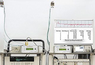
In the demo, software generates the 802.11AY signal. It runs on a Keysight M8195A AWG. This AWG provides up to 65 GSa/sec, 25 GHz bandwidth, 8 bits of vertical resolution, and up to four channels. It takes the form of a single-slot AXIe module. In the demo, it serves as a wideband IF signal generator.
The AWG puts out a signal centered at 4 GHz signal with four gigahertz of bandwidth. This signal ran into a VDI up converter to upconvert it to 61 GHz.This signal then passed to an amplifier/filter and then to a horn antenna. The signal passed to a second horn antenna and then to the high-frequency input of a Keysight 110 GHz UXA signal analyzer. In this case the analyzer serves as a means of down-converting the signal to an IF. It then runs into a scope that digitizes the signal and post-processes it to do the demodulation. The scope was a very high frequency version capable of reaching 63 GHz so it could digitize the millimeter wave signal directly.
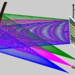
The demodulated signal was a 64 QAM constellation, very clean and centered at 61 GHz with 4 GHz of bandwidth transmitting over the air via the horn antennas.
Jue said the same basic setup can be used in different bands. This application used a converter from Virginia Diodes Inc. (VDI) going from 50 to 75 GHz. But for work at other bands, VDI also has convertors that operate in E band, 60 to 90 GHz or W band, 75 to a 110 GHz. Depending on which band you’re working in, you can swap this out with different convertors. The analyzer can operate all the way to 210 GHz.

Leave a Reply
You must be logged in to post a comment.