by Larry Sharp, Chroma Systems Solutions, Inc.
Functional and safety tests can show whether dc/dc converters perform the way their manufacturers claim they do.
DC-to-DC converters (DC/DC) are devices used to convert one dc voltage to another. Users and manufacturers may characterize DC/DC converters by running a variety of tests. We’ll describe several here, but the list is not intended to be all inclusive.
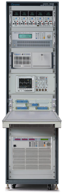
These tests can run manually or via an automated test system (ATS) with custom or dedicated software. These tests are intended to confirm that the DC/DC converters operate within their specified limits. They can be used for engineering product design verification tests, manufacturing production tests, incoming or receiving inspection tests, or qualification tests.
Here are some of the most common tests for DC/DC converters.
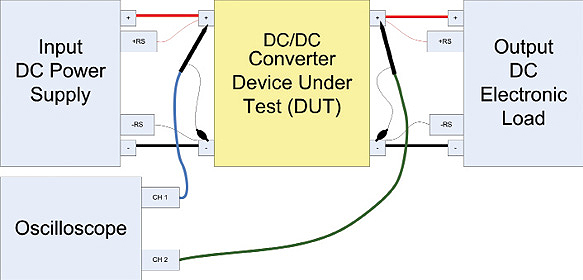
Input turn-on, input turn-off voltage levels and timing test : DC/DC converters have a specified input voltage operating range. To confirm the DC/DC converter works properly over the entire range of input voltages, they are tested using an adjustable or programmable dc source to provide the input voltage.
A dc electronic load is used on the output of the DC/DC converter to set the output load current and simulate the device that the DC/DC converter would power.
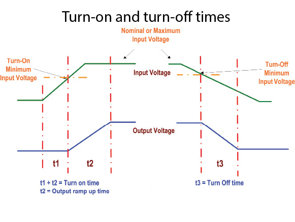
To test the minimum input voltage turn-on level, the DC/DC converter is turned on using the nominal input voltage while using the electronic load to apply the maximum rated output current or power. The input voltage is then reduced until the unit output begins to drop or the minimum input voltage setting is met.
To confirm the DC/DC converter would turn on with a maximum load on the output, the input voltage would be set to the minimum and toggled off and back on while measuring the output voltage and current. The output voltage and ripple and noise may also be measured to see if the lower input voltage setting has any effect on the output stability or ripple.
It’s important to use the remote sense leads from the dc power supply to insure the voltage at the DC/DC converter is set to the proper voltage. It’s also important to use the remote-sense on the dc load to insure the output voltage from the DC/DC converter is measured accurately. Additionally, this setup can be used to test and measure the turn-on time, turn-off time, and hold-up times. An oscilloscope is used for the ripple and for periodic and random deviation (PARD) measurements. Alternatively, a Chroma 63600 dc load can measure waveforms and display them for the applied voltage and current for as small as a 2 µsec sample rate, using a digitizing measurement feature.
Turn-on time indicates the period from the time at which the minimum input voltage is applied to the time the output voltage is within the output regulation limits. Turn-off time indicates when the input voltage drops below the specified minimum and the output turns off or drops to zero volts.
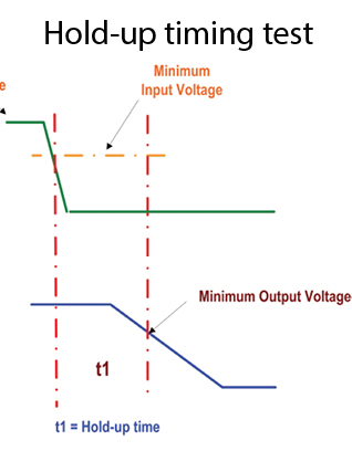
The hold-up timing test can use the same setup as the input turn-on and turn-off test. Hold-up timing indicates the time from when the input drops below the minimum input voltage and the output voltage drops below its minimum regulated output tolerance. This test also indicates how well the output of the DC/DC converter can continue to operate despite short interrupts and drops in the input voltage. Some DC/DC converters have an input fault detection signal. If so, this signal can be used to trigger the test. The Chroma 63600 load can use that trigger to capture and measure the hold-up timing without the need for an oscilloscope.
Output line regulation: This test confirms that the output voltage stays within specified regulation limits when the input voltage varies from minimum to maximum operating voltage, as defined in the DC/DC converter specification. During this test the output load is usually set to nominal or maximum current as specified.
The output line regulation test involves monitoring the output voltage and recording the total voltage deviation while varying the input voltage from its minimum to maximum specified limits. Some specifications show the output tolerance as a voltage (i.e. 3.3 Vdc ± 0.02 V) or as a percentage (i.e. 3.3 V ± 0.5%).
If the measurement accuracies of the output load and input dc source are adequate, then there’s no need for an external measurement device such as a DMM to measure the voltage, current and power. For example, the Chroma 63600 loads and 62000P dc power supplies have accurate measurements for voltage, current and power and need no external DMM. Some test systems include an oscilloscope to confirm the output voltage is stable during this test. Output regulation Ro is calculated as a percentage and given by the equation:
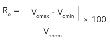
where:
Vomax = Vout at Vin max; Vomin = Vout at Vin min; and
Vonom = Vout nominal.
Output load regulation: The output load regulation test insures the DC/DC converter output voltage stays within the specified regulation tolerance. Here, the change in output voltage is recorded while load is varied from minimum to maximum current. This delta voltage is used to calculate the percentage of deviation which is compared to the specified load regulation limits. Load regulation Lr is calculated as a percentage from the equation:
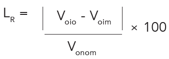
where:
Voio = Vout at Iout max; Voim = Vout at Iout min; and
Vonom = Vout nominal.
Output transient response deviation and time: This test determines how well the output voltage responds to a sudden change in output current. The measurement includes the maximum output voltage deviation and the time it takes for the voltage to recover to its regulated output nominal voltage tolerance.
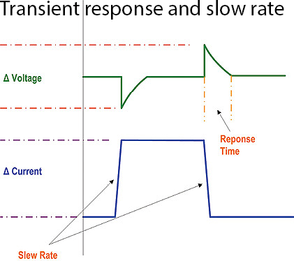
For this test, a dc electronic load is set for a minimum and maximum current and then set for the slew rate for the rising and falling edge of the current transition. The frequency and duty cycle can also be set for the pulsed current. The Chroma 63600 and 63200A loads can be programmed for all the settings required for a dynamic load and up to 50 Khz frequency with a duty cycle programmable from 1 to 99%.
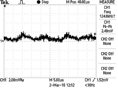
Output ripple and noise voltage: The output ripple and PARD reflects the output voltage of the DC/DC converter and its ability to filter out ripple and noise. Various topologies used in DC/DC converters have different internal switching frequencies which are reflected in the output ripple frequency. For example, internal chopper circuit transients can generate higher frequency noise. The output noise and ripple are measured using an oscilloscope, or with a dc electronic load (such as the Chroma 63600 where the output ripple can be displayed using the digitizing measurement function). To avoid erroneous noise, it is important to minimize the length of the ground wire on the voltage probe.
Output over-current protection: The output over-current protection is intended to protect the DC/DC converter and the device it powers when the load exceeds the converter’s maximum rated current. There are different methods used in over-current protection. But the typical approaches are fold-back current limit and pulsing current-limit. The latter is generally referred to as hiccup-mode current limit.
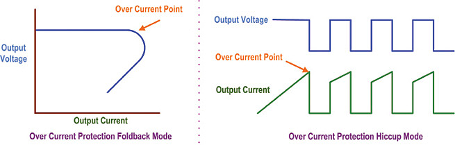
Here are the differences between the two methods: In fold-back current limiting, the output voltage begins to drop and limits the output current supplied to the load as the load current rises above the current-limit set point. In hiccup current limiting, the output turns off when the output current exceeds the rated current limit point. It eventually turns back on. If the load continues to exceed the current-limit set-point, the output will continue turning on and off, hence the hiccup-mode name.
Output over-voltage protection: Most DC/DC converters have a built-in protection circuit that will shut off the output of the device when the output voltage is detected to be over the maximum limit. This facility is referred to as over-voltage protection (OVP). This protects the DC/DC converter from external excessive voltage applied to the converter output. If the DC/DC converter has an adjustable output (trimmed or programmable output voltage), it may be possible to increase the output voltage until the OVP point is exceeded and the protection circuit activates.
If the DC/DC converter does not have an adjustable output, an external voltage source can be applied across the output terminal, increased to the OVP trip point, then removed to see if the output has triggered and turned off.
DC/DC converters having an OVP fault signal can use it to determine if the output detected the OVP and, if so, shut off the output. The output voltage is monitored to determine when the OVP happened and then compared to the OVP specified limits.
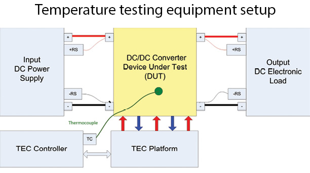
Output operating temperature and over-temperature protection: DC/DC converters have an operating temperature range, and many have an over-temperature protection (OTP) circuit that will turn off the output if temperature gets sufficiently high. For this test, a thermal chamber can raise and lower the DC/DC converter temperature to simulate the operating temperature range.
Thermocouples and thermal probes or infrared thermal measurement devices can measure the temperatures on the body of the DC/DC converter. During the operating temperature test, the DC/DC converter is loaded to its maximum rating for current and power. Meanwhile, the output voltage is monitored to verify it stays within specified limits.
During the test, the device temperature is recorded while monitoring the output voltage until the OTP circuit triggers and the output shuts off. The unit is then allowed to cool and input voltage is toggled off and on to verify the DC/DC converter recovers from the OTP.
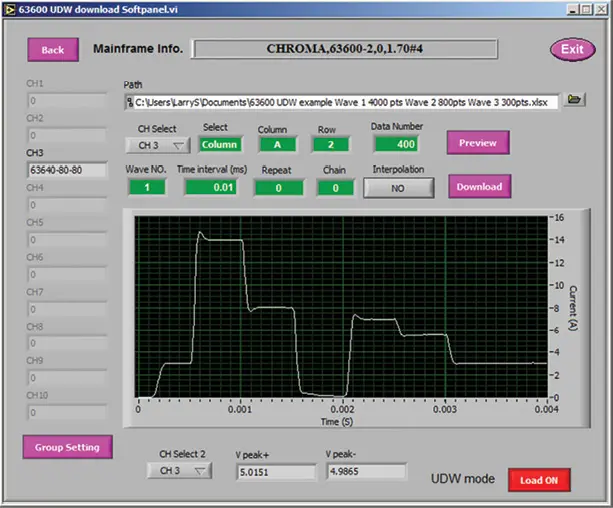
Custom load waveform simulation or real-world load simulation: Some DC/DC converters have applications characterized by a load with unusual dynamic changes and waveforms. An electronic load can replicate actual load waveforms to test the DC/DC converter under such conditions. One such family of dc electronic loads has user-defined waveforms up to 50 kHz and slew rates of 10 A/µsec. Waveforms can be stored and recalled manually or from the remote interface via USB, GPIB, or LAN.
Efficiency: Efficiency determines the internal power dissipated by the DC/DC converter and how efficiently input power transfers to the converter output. This test usually takes place at the nominal input voltage and with the output load set to nominal or maximum specified ratings. The input voltage, current, and power is measured while the same parameters are measured on the output. Efficiency percentage Ep comes from the equation:
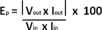
where:
Vout and Iout = converter output voltage and current;
Vin and Iin = converter input voltage and current.
This test can also capture the efficiency at various power levels. It’s common to plot the data to show efficiency versus output-current.
Output Trim Settings: For DC/DC converters that have adjustable outputs or that have trim settings, adjustments can be made manually or can be automated using programmable potentiometers or programmable resistor arrays. The test can be performed to verify the output adjustment range. All the previous tests can be performed to verify the DC/DC converter operates properly at different trim voltages.
Safety Testing
Safety dielectric voltage withstand tests, consider DC/DC converters that can be isolated or non-isolated. Isolated DC/DC converters have an isolation stage between the input and output. So they need functional insulation testing. Typically, if the input voltage exceeds 60 Vdc, the DC/DC converter may need to pass a basic insulation test.
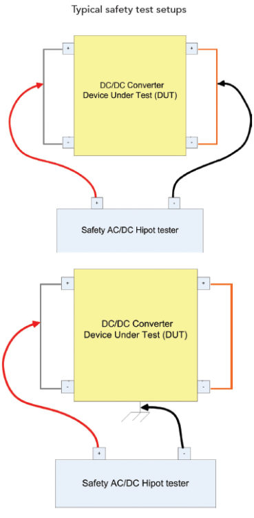
Also, if the converter has a connection to safety earth ground, a withstand-voltage test or hipot test will be necessary. This test can be and ac or dc-withstand test. The specific test withstand-voltage is specified by the associated standard. IEC 60950-1 is the standard for information technology equipment and covers a wide variety of devices.
References
Chroma Systems Solutions,
www.chromausa.com

Hi,how do I measure the output ripple of a boost converter using an oscilloscope?
Hi Ananya,
The best way to measure ripple in a boost converter using an oscilloscope is to connect a probe to the output and feed it into one of your analog channel inputs. Then, in the Tektronix 3000 series oscilloscopes, change DC coupling (the default) to AC coupling. Press Autoset if necessary and you will see the AC ripple if it is high enough to display. Its amplitude can be seen at the top of the display if you press Measure twice.
For safety testing, can we test from any input to earth, instead of both input to earth?
For a safety test, it is best to test both inputs to earth because an intrinsic impedance between the inputs could cause them to differ, and/or there could be an unexpected open circuit that develops causing different results in the two measurements.
So, How do you test the Isolated buck converter transformer?