The three-phase induction motor is ubiquitous in industrial applications because of its reliability and need for infrequent maintenance. Without brushes and externally commutated by the utility-supplied waveform, there is little that can go wrong. However, in the fullness of time and with a great many units operating in a large facility, stuff happens.
Here, we won’t discuss the variable-frequency drive (VFD), synchronous motor or single-phase installations; these are worth their own articles. For industrial applications, over 90% of all motors are induction types. Most of these that are not fractional horsepower units are three phase. (Where three-phase power is available, this is the way to go. These motors are less expensive, more efficient and — with three wires not counting the equipment ground — the conductors are smaller and easier to install.)
First the basics. Motor bearings and field coils rigidly mount on the inside of the motor enclosure. The shaft and commutator, if any, collectively known as the armature, are supported by the bearings so they can freely turn without off-axis motion.
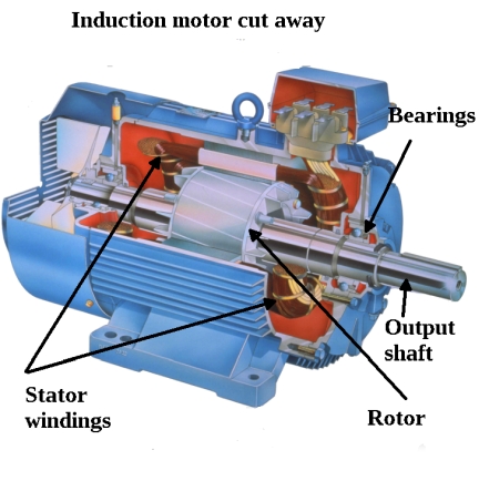
The rotor and stator produce magnetic fields. One but not both of these components may consist of permanent magnets or soft iron bodies that exhibit magnetic reluctance. The mechanism by which the motor turns differs depending on its type. In a dc motor, the electrical current and hence magnetic field must reverse polarity periodically so the turning magnetic field of the rotor is always chasing the stationary magnetic field produced by the field coils. The continually reversing magnetic field associated with the armature is made possible by oscillating electrical current that passes into the armature through brushes that ride along the commutator. The commutator is made of reverse-connected adjacent conductive segments that are insulated from one another.
Thus the brushes perform the dual function of introducing the electrical energy into the armature and rapidly switching polarity so the magnetic field reverses as needed. Without the switching action, the rotary motion would consist at best of one-half turn, and then the rotor would remain at rest.
The ac synchronous motor also consists of one magnetic field continuously seeking the other, but commutation is accomplished in an entirely different manner. The reversing current is actually due to the rotary nature of the generating facility’s spinning turbines. Because of this arrangement, the ac synchronous motor, like a ac brushless motor, is said to be externally commutated.
There is still, in the ac synchronous motor, the irksome matter of getting the current into the armature. Unlike the field coils, the armature is turning and cannot be directly wired. Here again, brushes are needed, and this is a relatively expensive, high-maintenance solution. In this context, we see the great advantage of the induction motor, which accounts for its overwhelming popularity in rotary applications worldwide.
In the induction motor the field windings and the rotor windings behave electrically like the primary and secondary of a simple ac transformer. AC electrical power from outside the motor connects to the induction motor’s field windings, setting up an oscillating magnetic field. This induces an electrical current in the rotor along with a magnetic field. As a consequence, the armature, with no direct electrical input, begins to rotate. The rotation can be harnessed to perform useful work by means of an output shaft.
The rotor’s rotary motion is not directly synchronized with the turning magnetic field associated with the field coils. (The induction motor is also called an asynchronous motor.) In fact, the field coil magnetic field and the rotor turn at different rates, the ratio between them usually expressed as a percentage, typically below 10%. This percentage is known as slip, which is relevant only in induction motors. With a locked rotor, slip is 100%. When fully loaded, slip can range from 1% in large induction motors to 6% in fractional horsepower motors. Slip should not be understood as wasted motion. It is intrinsic to all induction motors and without slip they would not turn at all.
Usually an industrial induction motor is a three-phase unit whose output shaft drives a load such as fan, conveyer belt, augur, saw blade or crusher. It is powered by electrical energy from the output of a VFD or suitable controller.
An induction motor not powered by a VFD typically has utility-supplied power at its terminals. This power may be turned on and off by the controller, and any two legs it may be switched so as to reverse the direction of rotation. But voltage and frequency are not modified, appearing at the motor terminals as supplied by the utility. Duty cycle and pulse width are not applicable where a VFD is not in the picture.
Eventually induction motors may exhibit problematic symptoms. These could consist of one or more of the following:
• Abnormal temperature rise as measured on the surface of the motor housing. If the highest temperature is measured at a bearing, it may lack lubrication or need to be changed. In an extreme case, a loose bearing may let the rotor rub on the stator. Be sure that dust or other material has not built up on the outside or inside of the enclosure and that air circulation is not impeded.
• Reduced RPM, usually accompanied by temperature rise, measured at the output shaft or is apparent in the load.
• Increased current measured at the leads connected to the motor terminals. This high current also is often accompanied by temperature rise. The current often causes the over-current devices to trip out, the extreme case being that the motor will fail to start.
Frequently poor motor performance is caused by a binding or mismatched load so it is not the fault of the motor, although the motor can be damaged if the condition is allowed to persist. When there is a problem, the motor should not be run in hopes that it will get better on its own. It will only get worse, and in the process motor windings or internal insulation will be damaged by the heat.
After ruling out bearing, drive, and load malfunction, next on the agenda are electrical measurements. A multimeter in conjunction with an electrician’s clamp-on ammeter will provide useful information, but an oscilloscope is better. What we need to do is view the utility power waveform to make an assessment of the power quality. Low line voltage, phase imbalance or a dropped phase, intermittent noise caused by a poor connection, or harmful harmonics can cause poor motor performance, and all of these can be quickly spotted in an oscilloscope display.
For motor measurements in the field, a hand-held, battery-powered oscilloscope is the best choice. The ruggedized rubber case and environmentally protected electronics are suitable for harsh conditions characteristic of the factory floor or outdoor surroundings.
More important, in contrast to the grounded bench-type instrument, the hand-held oscilloscope has channels that are isolated from ground and from each other, so there is no danger of an intense fault current if the ground return lead is connected to a wire or terminal referenced to but floating above ground potential. Most portable oscilloscopes are safe from this point of view, but it is best to check the manufacturer’s literature to be sure.
When a large motor is first installed and found to be operating correctly, it is a good practice to take oscilloscope readings, record the results, and repeat the readings at regular intervals so a database can be established. Then, readings taken after the start of abnormal operation will be more meaningful.
To get a complete picture, scope readings should be taken at accessible locations starting with the mains at the electrical service, then working downstream to the input and output of the disconnect and motor controller and finally at the motor input terminals. These readings should be taken with the motor running, with the load engaged and not engaged, and also with the motor not running. Both voltage and current measurements should be taken. If the problem is intermittent, measurements may have to be taken continuously and the results logged. Sometimes power quality problems arise from other equipment in the same facility or the sharing of a utility line. Perhaps the problems happen only during working hours, when specific equipment runs. In making these measurements, the important metrics are:
• Input voltage: 10% is often given as the maximum permissible deviation from nominal, with the motor fully loaded, but this amount can bring a shortened motor life, particularly because during startup, the motor will draw heavy current, further dropping voltage at the motor input. Low voltage can come from internal motor wear, mismatch or binding in the load, inadequate branch circuit size, heavy loading in nearby equipment, or a poor utility supply. A high voltage reading is unusual, most likely due to an anomaly in the utility.
• Voltage and/or current imbalance: 5% deviation between legs can cause motor heating and shorten motor life. Sometimes imbalance can be reduced by rolling the connections without reversing any two of them. But more often it is a sign that the motor must be rewound or replaced. Another possibility, however, is that the problem is external. To find out, make sure any outside loads are disconnected and that all cabling and terminations are intact. Then repeat the voltage and current measurements.
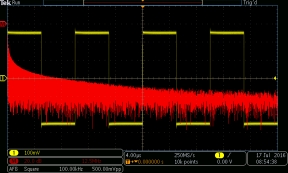
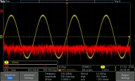
• Oscilloscope waveform measurements: The asynchronous induction motor, like other ac motors, thrives on current that is a pure sine wave. For example, if the motor is powered by a square wave as produced by an old-style inverter, the motor will run hot and fail prematurely. Similarly, if the waveform is noisy, clipped or has spikes where there should be none, motor operation will be problematic. In the time domain, the waveform at the motor terminals can be viewed with and without the motor running and with and without the load connected.
Harmonics can be a cause of motor overheating and frequent trip-outs. Harmonics can be measured by viewing the electrical supply at the motor input terminals in the frequency domain. Modern oscilloscopes have this capability, which is generally accessed by pressing a button labeled Math. Then go to Fast Fourier Transform (FFT) and you will see a representation of the signal in the frequency domain.
As in the conventional time domain, the Y-axis represents amplitude. Rather than voltage, power is displayed, calibrated for readability in a logarithmic dB scale. The X-axis represents frequency. A good sine wave will have a single strong spike at the fundamental, the only other irregularity in the graph being the noise floor of the oscilloscope.
A signal that corresponds to a defective power supply will have a somewhat reduced peak at the fundamental and additional spikes that correspond to harmonics. Eliminating these harmonics will result in improved motor operation.
These readings should be taken with and without the motor running, and that is a start in locating the source of the harmonics. This is a good example of where early readings while the motor is operating normally are valuable in making sense of the oscilloscope display.

Excellent article. Thanks so much.
Due to really poor power quality in my lab at work, I needed to build or buy some fairly extensive and expensive power conditioning equipment.
I chose to build it myself. This group spends fortunes on mechanical tooling but skimps on electronics T&M gear, etc. The power quality here noises up low level (uA) current measurements and pounds noise into every instrument on the mains. The USA convention of bonding neutral and ground at the subpanel is bad news in industrial factory settings where so much power is quickly switched on and off the distribution network.
I settled on using an approach that worked for me in the semiconductor, cellular and broadcast sectors: balanced power…
I just needed a way to easily shift one phase of the 50hz either 60 degrees or 120 degrees.
Your article gave me enough information to understand how I could use an induction motor, an autotransformer and a capacitor to change phase by simply rotating the shafts and then locking it down.
Your article also suggests to me that the induction motor, etc, might be a pretty decent ferromagnetic isolation transformer to boot!
Best regards,
Pete