“Bus” is an old term derived from conductive elements that are part of an electrical distribution system, generally referring to short specialized conductors separate from the overhead or underground cable. Typically, the old-style buses consist of bare copper bars, often having a rectangular cross-section, firmly mounted in an enclosure and capable of carrying current at substantial voltage.
In contrast, the first data buses consisted of bundled insulated wires in a parallel configuration, with soldered or plug-connected terminations. Over the years there has been a decisive, though not total, shift from parallel to serial transmission, which has the advantage of less wire, with greater immunity to crosstalk, noise and data loss.
Each digital bus is unique in regard to the ways it is accessed and displayed in an oscilloscope for purposes of troubleshooting or system design. One of the more widely used digital buses is the I2C which stands for inter-integrated circuit. The superscript is just a handy abbreviation and does not signify a mathematical operation.
I2C, first offered by Philips Semiconductor in 1982, is a synchronous, multimaster-slave, packet switched, single-ended, serial bus that connects ICs to processors. It typically consists of copper traces on individual printed circuit boards, in some cases with wires joining multiple boards.
Since 2006, I2C has been open source, meaning that all manufacturers can offer the bus without paying fees except to obtain I2C slave addresses.

There has been massive migration from parallel to serial data transmission, with significant savings and enhanced performance. The one problematic aspect has been for serial distribution troubleshooting and design prototyping, there has been a steep learning curve. The reason is that all the masters and slaves would like to talk at once, so complex mechanisms have to be in place to arbitrate among them.
Two-wire master-slave connectivity is the basis for I2C. There can be any number of masters and slaves on a single two-wire serial bus. All masters and slaves are connected in parallel between the two lines in the manner of receptacles in a residential branch circuit. A logic High voltage is applied to one of the lines, and if any master or slave conducts, it is pulled down. Of the two lines, one is a serial data line and the other is a clock line. By conducting or not conducting, any master or slave can write data that any other device can see.
All masters monitor the bus for start or stop bits. If a master is using a bus, another master will not interrupt. When two masters begin simultaneously, the one sending a message to the slave having the lower slave address will have priority.
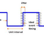
The I2C protocol is generated by a bidirectional data line, dubbed SDA (receives I2C pattern and transmits an acknowledgment when communication is successful) and a clock line dubbed SCL. Each slave device is identified with a different seven-bit address. Transfers are initiated by a start condition (SDA falling edge while SCL is high). Transfers end with a stop condition (rising edge on SDA while SCL is high).
An instruction is sent through the SDA in blocks of one byte, where the first bit is the most-significant bit. SDA bits must be stable while SCL is high, and they must change while the SCL line is low. If SDA bits are unstable while SCL is high, the situation is interpreted as a stop or start condition, a typical cause for a corrupted message or missing acknowledgment. The number of bytes transmitted is unlimited; each byte must be followed by an acknowledgment bit from the slave confirming the successful reception of the byte.
The usual approach in designing I2C circuits is to first develop the master, then test it with a test slave, basically a shell of the design that provides test hooks. The platform for the test slave is generally the microcontroller used for the slave development.
Tests of I2C circuits generally focus on three areas: the electrical qualities of the bus itself, timing, and how to handle exceptions. For example, it is possible that the delay between SCL and SDA is too long. In those cases, unwanted START or STOP conditions can arise in the middle of theI2C pattern sent, causing the slave to get a different message or resulting in a missing acknowledgment.
Similarly, an unsuccessful execution results in the case of missing or unexpected SCL pulses. If something unexpected happens, it is assured by design that a START condition discards the previous incomplete or erroneous message, and the device is ready to receive the new message.
Other problems can arise when less than eight bits are sent. The slave will wait for the rest of the data in this case. Unless the eighth bit is sent, the slave does not generate an acknowledgment.
When a block operation takes place, the number of bytes to be sent or received may already be fixed in another register. If the number of bytes sent or received is less than the number expected, the state machine waits for the rest of the message. The start condition can be patterned to skip the waiting state.
Additionally, the master must work with the response and timing qualities of the slaves. Sensitivity to these issues can generally only be determined through testing rather than analysis. In particular, the slave may make emergency calls or interrupts to the master. Tests of how they happen and the resulting responses may reveal difficulties in the I2C interface.
The usual approach is to create a surrogate slave to support testing the master. The main role of the surrogate slave is for interface testing and verification. Thus the surrogate may have more functions than real slaves, simply for the purposes of testing.
There are several means of making tests of I2C circuits. One is the Tektronix Demo 1 board which is intended to go with a Tektronix MSO4000 oscilloscope, but which also works well with the MDO3000 models. It provides numerous serial bus signals including dedicated terminals for I2C. The board comes with a specialized T-type USB cable with two USB Type A connectors at one end. Both of them are to be plugged into separate USB slots on the oscilloscope, to assure sufficient current-carrying capacity.
One red and two green LED’s indicate that the board is receiving power and ready for use. Having seen I2C serial bus signals acquired from the demo board, you can connect the probes to similar terminals (consult schematic and data sheets) in non-functioning equipment and see what you need to do to acquire a signal.

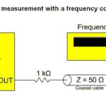
One inexpensive (about $30) way of testing I2C circuits is the Bus Pirate, a universal bus interface that talks to most chips from a PC serial terminal. It supports many serial protocols at 0-5.5 V. It includes a number of handy features such as a 0-6-V measurement probe, 1 Hz to 40 MHz frequency measurement, a 1 kHz to 4 MHz pulse-width modulator/frequency generator, on-board multi-voltage pull-up resistors, macros for common operations, bus traffic sniffers, a bootloader for easy firmware updates, a 10 Hz to 1 MHz SUMP-compatible logic analyzer, and numerous other helpful artifacts.
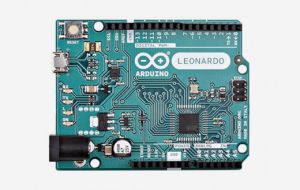
Another open-source testing regime is called userial. It is a free USB to I²C/SPI/GPIO bridge, using an Atmel chip as resides on Arduino Leonardo boards. Besides I2C, it also supports
1 × USB interface (serial emulation)
1 × JTAG interface
1 × SPI
8 × General purpose digital I/O (GPIO)
4 × Analogue to Digital converters (ADC)
The board communicates with the host computer using a CDC (USB communications device class). This makes it easy to use userial without installing a device driver or special libraries. Use of an ASCII-based command interface makes it easy to control devices manually with just a terminal emulation.


Leave a Reply
You must be logged in to post a comment.