The National Electrical Code in Article 430 specifies that all electrical motors are to have suitable controllers. When the motor runs at a constant speed, the controller can be relatively simple. It is often not much more than an on/off switch, though there are more sophisticated versions that include provisions for handling different types of motor overloads and which reduce the stress on the motor during start-up.
For a stationary motor of 1⁄8 hp or less that is left running and cannot be damaged by overload or failure to start, they can be as simple as the branch-circuit disconnecting means. An example is a wall clock that is protected by a circuit breaker or fuse in the entrance panel. The next step up is a portable motor rated 1⁄3 hp or less. The controller for this motor is permitted to be an attachment plug and receptacle or cord connector.
A branch-circuit inverse-time circuit breaker rated in amps is permitted for all motors. Inverse-time circuit breakers have both a thermal and an instantaneous trip. They are the most common type of circuit breaker found in residential, commercial, 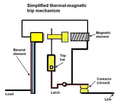 and heavy construction uses. Their thermal action responds to heat. In the event of a short, the magnetic action of the circuit breaker will detect the instantaneous values of current and trip the breaker. The National Electrical Code requires inverse time circuit breakers to be sized to a maximum of 250% of the motor full-load amperage (FLA).
A simpler type of breaker is the instantaneous-trip type which responds to immediate (almost instantaneous) values of current from a short circuit, ground fault, or locked rotor current. This type won’t trip from a slow heat buildup. The National Electrical Code allows instantaneous-trip circuit breakers to be sized to a maximum of 800% of a motors FLA value. Some instantaneous-trip circuit breakers have adjustable trip settings which can be adjusted above the locked-rotor current of a motor to allow the motor to start and come up to its running speed.
For stationary motors rated at less than two horsepower and 300 V, the controller may be a general-use switch having a rating of not less than twice the full-load current of the motor. On ac circuits, a general-use snap switch suitable for use only on ac (not general-use ac-dc snap switches) is permitted as the controller, where the motor full-load current rating is not more than 80% of the ampere rating of the switch.
The controller is not required to open all conductors to the motor unless the controller also serves as the disconnecting means for the motor. Thus, for a 240-V, single-phase motor, unlike an in-circuit switch, the controller could open just one leg, and this would stop the motor, though one of the terminals would remain live. For a three-phase motor, two legs would have to be opened to ensure the motor would not continue to run on two phases. With exceptions, each motor is to be provided with an individual controller.
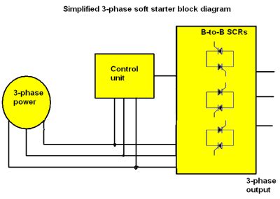 In contrast to these types of motor controllers, soft starters adjust the motor voltage on start-up as a means of controlling motor current and torque. They generally do so through use of solid-state devices like SCRs. The basic principle of soft starting is that controlling the conduction angle of the SCRs controls the application of the supply voltage. The starter uses the fact that the torque is proportional to the square of the starting current, which in turn is proportional to the applied voltage.
Soft starters can be both open loop and closed loop. Open-loop starters apply a start voltage irrespective of the motor current or speed. For each motor phase, two SCRs connect back-to-back, and the SCRs conduct initially at a delay of 180° during the respective half-wave cycles (for which each SCR conducts). This delay is reduced gradually with time until the applied voltage ramps up to the full supply voltage.
Closed-loop soft starters monitor any of the motor output qualities such as the current drawn or the speed, then modify the starting voltage accordingly. If current in each phase exceeds a certain set point, the time voltage ramp is halted.
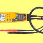
Trouble-shooting and checks of motor controls generally involve test equipment that includes a megohmeter (minimum 500 V output), a clampmeter with multiple jaw sizes, a magnetic compass (for identifying motor field coil polarities), and a digital multimeter (minimum 600 V, CAT III true RMS rating, with low resistance (0.01 Ω or lower) featuring a cycle function and capacitance test.
Though it may sound obvious, part of motor control troubleshooting involves determining whether the problem is the motor control or the motor itself. That’s why with the power switched off, a first step is to turn the motor shaft to determine if it rotates freely, listening for unusual noises such as scraping, smelling for burned insulation, and feeling for excess heat. Visually inspect the motor starter for loose connections and discolored hot spots. All fasteners and mounting hardware should be checked and re-tightened.
Next, manually engage the starter and measure the resistance through its contacts. A reading of 0.09 Ω or less is good. Disengage the starter and then use the megohmmeter to ground-test the line and load circuits at the starter. This test will effectively identify the resistance-to-ground of the starter, line circuits to the disconnect, and load lines to the motor and starter windings.
Generally, ac devices can safely operate at not less than 2 MΩ to ground, and dc devices can safely operate at not less than one 1 MΩ to ground. But note that before ground testing, any electronic controls are disconnected. They can be destroyed by misapplied high-voltage test equipment.
The resistance reading depends on the horsepower of the motor. For example, a 50-hp motor should ideally show 0.05-Ω resistance. Measurements between phases should be roughly equivalent. The exact measurement value is less important than balance between phases. Though the readings won’t be identical, they should be close. Resistance measurements are also helpful in single-phase and dc motors where they can identify open circuits.
Also check each fuse for continuity (one fuse per phase). A blown fuse is a symptom rather than cause, so replacing a fuse won’t fix the motor. Check the fuse holders for spring tension — repeated fuse replacement can compromise the spring tension needed for good contact. Signs a fuse holder has lost tension include pinhead-sized arc damage anywhere on the clip, fuse, or surrounding areas. Also inspect breakers and buses for overheating and arc damage, as well as connectors.
Check the voltage value and balance on the line (supply) side of the fuseholder. Because this is a line-to-line check, operating voltage has no path to ground. But an unreasonable voltage imbalance between any two phases is a problem. A 5% voltage unbalance is normal.
Next comes a check of the connections inside the motor lead junction box. Many motor failures arise from poorly installed wire nuts or insufficiently insulated connections that get grounded inside the junction box or that short together.
Checks that reveal low ground readings or open readings at the load side of the starter indicate the need for a test of the stator winding phase resistance and resistance-to-ground. This test helps determine whether the problem is in the motor or in the line circuit. The procedure begins by first breaking the motor connections and then testing first in one direction (the motor), then in the other (the supply).
On the motor, test the stator winding resistance phase-to-phase and phase-to-ground. A phase-on-phase short indicates the motor needs an overhaul or replacement. Sometimes motors can be repaired if there is a phase-to-ground short.
The supply is first tested with the motor disconnect open and locked out. Then the megohmmeter can be used to test the insulation resistance to ground. If the wiring fails the test, there can be problems in the connections or a failure in the conductor insulation.
In the case of soft starters, these controllers often provide error messages in the event of a problem. If the error message is less than illuminating about the source of the difficulty, factors to check include the absence of a phase and a short in one of the SCRs in the soft starter itself. Also check whether the motor and grid voltages are abnormal.
Once the problems are identified, it’s time for a test run. Energize the motor, note the operating voltage and current, check the balance, and verify that measurements are within the nameplate specifications. There should be no unusual noises, no smell of smoke or hot insulation, the motor should run cool and should not be vibrating excessively. Then engage the load and do a final noise/smell/heat/vibration assessment. Hopefully, everything runs smoothly.


Leave a Reply
You must be logged in to post a comment.