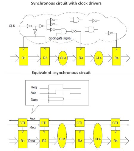
Traditionally, computer and instrumentation engineers work with synchronous logic, where a global clock circuit imposes a timing structure to which all circuits down to the components level adhere. In synchronous logic, an autonomous oscillator outputs a square wave that never varies in frequency or amplitude. At the rising edge (sometimes falling edge) a potentially vast number of circuits enter specific states and perform their appointed tasks.
Asynchronous circuits are far less common at present, but they may well become the wave of the future because of specific advantages they have over synchronous circuits. They also have disadvantages, which accounts for the current unresolved state of affairs.

Asynchronous circuits have the potential for being faster and requiring less power, which is critical in small, portable devices like cell phones and digital cameras. They are also less prone to electromagnetic interference.
Together, synchronous and asynchronous logic comprise sequential as opposed to combinational logic. Sequential logic is the basis for modern digital circuitry. In sequential logic, the clock signal is applied to each of the flip-flops, which are the memory devices. Changes in these ubiquitous elements occur in response to the clock signal, specifically at a waveform edge.
In synchronous circuits, the clock frequency must be low enough to let the output of even the slower logic gates stabilize prior to the next clock cycle. This mode of operation enables reliability, but it does constrain overall speed. The logic path having the longest propagation time becomes the bottleneck. Some circuits have relatively long idle time while they are waiting for slower circuits to finish, which equates to high power consumption and heat dissipation with all that entails.
To meet these multiple challenges, designers have turned to the notion of asynchronous logic. Here there is no clock signal, which is to say that the circuit is self-timed. In asynchronous logic, change-of-state is initiated by signals that correspond to the completion of the current operation.
Because there is no clock signal, asynchronous logic is characterized by the fact that the circuit state depends upon a change solely at its input(s). The process, in contrast to but still in the context of the synchronous protocol, is not retarded by delays inherent in clock timing. Speed is constrained only by propagation delay among the logic gates.
A problem in this partial solution, however, is the disparity between arrival times of signals at the various logic gate inputs. A race condition arises when signals appear at gate inputs simultaneously or closely in time. This may result in one or more circuits entering the wrong state. To avoid such difficulties, asynchronous circuits may contain more gates than their functionally equivalent synchronous counterparts. The additional gates may boost delay times.
Also, asynchronous circuits must explicitly generate their own sequence control — usually request and acknowledge handshaking signals. In synchronous circuits, the clock signal handles this chore. The generation of these explicit control signals further complicates the asynchronous circuitry and slows circuit operation.
A large amount of engineering expertise has been deployed to resolve this impasse. One answer has been bundled delay, and another has been delay-insensitive circuitry. The bundled delay depends upon locally generated delay, which has the advantage of small size. Delay-insensitive design allows for arbitrary delays by permitting layouts that compensate for timing fluctuations that are intrinsic in asynchronous logic. Quasi-delay-insensitive design has been implemented with partial success.
Another asynchronous structure is called a micropipeline. In principle, an asynchronous pipeline may pass data to its neighbor whenever the stage is done and the neighbor is free. Different stages may operate at different speeds and stages may complete early depending on the actual data. Micropipelines have alternating computation stages separated by storage elements and control circuitry. They use transition signaling for control along with bundled data.
Despite difficulties, there are numerous advantages on asynchronicity. Foremost among them is lower power consumption, which is realized in multiple ways. One of these is because semiconductors that are not continuously transitioning, as in clock-driven designs, remain quiescent a greater fraction of the time. Additionally, the clock itself consumes power and dissipates heat.
Unlike synchronous circuits, which become less reliable and consume power due to fan out, asynchronous circuits are connected in a more streamlined fashion. And rather than committed to a set clock speed, asynchronous circuits are compatible with line voltage and ambient temperature variations and are not committed to a specific timing frequency. This added flexibility makes possible new energy reduction strategies.
Because the manufacturing process introduces component variations, synchronous methods are not necessarily the most energy-efficient. Moreover, synchronous circuits create electromagnetic interference close in frequency to the clock fundamental and harmonics, whereas EMI deriving from asynchronous circuits because it is less spectrally focused, cause less severe effects in nearby equipment.
An increasingly prominent disadvantage in synchronous logic is reduced speed. As in many difficulties in electronic design, there is a workaround. It consists of splitting complex operations into simpler parts, which then need not be executed in the same clock cycle. This technique is known as pipelining.
Techniques that verify logic design — including circuit verification, timing analysis, and testing — become critical for asynchronous logic because of the subtlety involved. There are a large variety of asynchronous design approaches, so there’s no single approach to analyzing and verifying asynchronous circuits. But we can describe a couple of techniques that give a flavor for the area.
One method is called trace theory. The logic system is described by the set of possible event sequences (i.e. traces) that can happen. Each trace represents one possible interleaved behavior of the logic. Traces are combined into a set which defines the observable logical behavior. The sets get compared to a standard which defines what the circuit is supposed to do.
The tracing technique is good at finding problems caused by incorrect logical behavior. It isn’t as good at finding problems caused by timing issues (such as propagation delays) within the asynchronous logic.
However, there have been academic tools developed to carry out timing reliability studies on asynchronous logic circuits. They generally focus on determining the minimum and maximum time separation of events.
Asynchronous logic has special design constraints that complicate any kind of testing. For example, asynchronous logic designs often incorporate redundant logic to eliminate possible erroneous logic levels caused by glitches. The redundant circuitry makes testing more difficult.
Synchronous logic chips often incorporate a serial scan path which creates a shift register out of storage components on the chip. External test logic reads and writes to the shift register to verify that the IC goes into the proper states as it gets a series of clock pulses.
Serial scan can also be used to test asynchronous circuits but its implementation is more complicated. Synchronous circuits have many feedback loops that cannot be controlled by an external signal. This forces the circuit designer to help develop the functional test, either producing the scan patterns directly or building in the design-for-test measures.
One problem with applying scan paths to asynchronous logic is that different parts of the logic don’t all change state at the same time — so it is less straightforward to single-step the circuit through a sequence of well-defined states. In turn, it is more difficult to get the circuit into particular quiescent states, necessary to check for short and open faults that are typical in modern CMOS processes.
Also, asynchronous circuits tend to implement registers using latches rather than flip-flops. It tends to be more complicated to connect latch-based registers in scan paths.


Leave a Reply
You must be logged in to post a comment.