Cat 5e (enhanced) cable is widely used in local area networks (LANs), telephone and video. It works well in applications that call for unshielded twisted pair (UTP) and telephone zone wiring in a star configuration. Two telephone lines can be run and two extra pairs are available for future use. Using modular RJ-45 connectors, a Cat 5e installation enables 10BASE-T, 100BASE-T, 1000BASE-T and 10GBASE-T, with speeds of 10 Mbit/sec, 100 Mbit/sec, 1 Gbit/sec and 10 GBit/sec with acceptable performance at up to 100 m between active repeaters. For Ethernet LAN lines, crimp-on connectors must be used, but for telephone lines, small blue wire nuts suffice.
Cat 5e normally consists of four twisted pairs, each with a slightly different twist rate, ranging from 50 to 75 turns/m, to discourage cross-talk. Twisting in conjunction with differential signaling as used in Ethernet greatly minimizes noise from outside because common-mode rejection eliminates unwanted current induced in both conductors equally. Good performance requires that the twisting is maintained as close as possible into terminations. RJ-45 crimp-on conductors are therefore quite suitable. (Cat 6a has a higher twist rate and better performance, but due to the higher cost it is not used in most LAN installations.)

There are two termination standards, T568A and T568B. Using either of these standards at both ends results in what is known as the straight-through wiring configuration. Using T568A and T568B at the other end results in the crossover configuration. The choice of straight-through or crossover terminations is based on the type of devices present at the two ends. The difference is in the positions of the two pins used for transmit and the two pins used for receive. The network will not work if transmit and receive are not connected.

Hubs and switches have MDI-X ports, with internal crossover. Routers, servers and end hosts such as PCs have uplink ports. When devices with the same type of ports are connected, a crossover cable is used. When devices with different port types are connected, a straight-through cable is used. (Connecting a computer to a hub or switch requires a straight-through cable. Connecting two computers, switches or hubs requires a crossover cable.) In reality, devices currently manufactured automatically detect and implement the proper configuration, so straight-through and crossover cables can be used interchangeably. But it is better if the proper type is labled and used in case a device is replaced in the future.
Short patch cords of either type are readily available. For long runs, especially those to be concealed by finish surfaces or fished through existing cavities, it is customary to run the cable first, then field-terminate the two ends. Copper category cable is available with either stranded or solid conductors. Stranded is generally used for patch cords, where greater flexibility is desirable, and solid is preferred for permanent installations.
In LANs, Metropolitan Area Networks (MAN’s) and Wide Area Networks (WAN’s), Ethernet is by far the predominant technology. In the past, coaxial and other cables were used, but currently what you see is category cable, primarily Cat 5e unshielded twisted pair (UTP) or optical fiber. The exception is wireless transmission. Whether the medium is cable or Wi-Fi, Ethernet packets are generated, conveyed and processed in the same way. Wi-Fi is highly favored in residential and commercial applications because it is quick and easy, eliminating wire clutter and installation labor at the expense of a slightly less stable connection and the need for password protection.
An Ethernet transmission consists of short segments known as frames. Source and destination addresses are specified in each frame. Defective frames are detected, discarded and replaced. Each Ethernet frame includes 48-bit MAC addresses specifying source and destination. By means of these elements, link-level connections are created. A receiver reads the destination address to determine whether the transmission is relevant or should be ignored. All of this is backward compatible, so new-generation devices can be used in existing networks. The frame format does not change.
Earlier computers required an external network card, but today a network interface is part of the computer motherboard. Contemporary Ethernet stations communicate through switches, which convey Ethernet packets to the appropriate destination. Collisions are greatly reduced, arising only when station and switch attempt to communicate simultaneously. The collisions are confined to a single link. Moreover, full-duplex communication was introduced in the 10Base-T standard, and it is used in Fast Ethernet and Gigabit networks. These implementations are entirely free of data collisions.
In building a data network, an important final step is testing and certifying it. Specialized test equipment is available for use with optical and fiber media.

An optical time domain reflectometer (OTDR) is used to test and evaluate optical fiber links. The instrument injects light pulses at one end of the fiber being tested and, at the same end, detects light reflected from one or more points in the link. The return pulses are measured and timed so the location of any anomalies and other relevant data may be known.
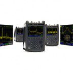
A bench-type OTDR has numerous features not found in the more portable hand-held, battery-powered instruments. Both types are efficient and accurate fiber-break locators and provide other information as well. The latest hand-held OTDRs are suitable for collecting data in the field. Besides fiber breaks, they measure and locate points of high loss or reflectance, end-to-end loss, and optical return loss. Data can be stored and later downloaded to a PC, with appropriate software installed, for further analysis or to be emailed to a colleague.

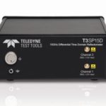
A time domain reflectometer, available in bench-type and portable models, may be optimized for evaluating copper data links in UTP or coaxial cable. Here again a pulse, now electrical rather than light, is injected into one end of the link under investigation, and at the same end any reflection is timed and analyzed. If the cable is of uniform and correct characteristic impedance, with proper termination, there will be no reflections, indicating a good link. With no reflections, it is impossible to ascertain the length of the cable. However, such is the sensitivity of the instrument that even in a close-to-perfect cable there will be some slight variation that will create a small and harmless reflection that can be used to gauge the length.
If the cable is shorted at the far end, the transmitted pulse is not absorbed as it would be if the cable impedance matched the load impedance. Accordingly, at the source the voltage drops to zero. By measuring the time interval, the distance to the short can be determined.
If at the far end there is an open circuit (infinite impedance), the return pulse adds to the source voltage because it is of the same polarity, and the time interval will be indicative of the fault location.
TDR analysis has many diverse applications, other than evaluating data links and locating faults. An example is detecting and locating illicite wiretaps, which create discontinuities that give rise to reflections. Another example is the non-destructive mapping-out of reinforcing rod in large concrete structures such as dams. Still another example is locating an electrical fault in concealed wiring of a large aircraft. Additionally, time-domain reflectometry is used in checking circuit boards, where soldering faults that are difficult to see are revealed due to discontinuities.
 TDRs are quite expensive, and if you do not perform these measurements professionally on a regular basis, you may not be able to justify the expense. But if you are reading this, chances are you have an oscilloscope and a signal generator.
The hookup and math are fairly complex. (The advantage of a factory-made time domain reflectometer is that it is user-friendly and does the math for you, displaying the results in a manner that can be easily communicated.) There are lots of plans and discussions on the Internet. The best explanation that I have seen may be viewed here.


thanks for providing useful information on Testing Cat 5e unshielded twisted pair cable and Ethernet connections