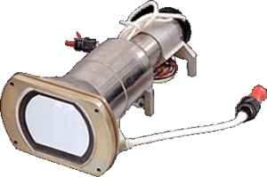
The cathode ray tube (CRT) is what made possible TVs, computer monitors, and oscilloscopes as we know them. CRTs have largely been replaced by flat-screen technologies but CRTs still serve in niche applications. For example, some kinds of military needs still require a CRT display. General-purpose CRTs are no longer manufactured in the U.S., but factories in China and India still make them — for use in TVs, not computer monitors. One consumer application that still requires CRTs is that of monitors for arcade games. Also, a few perfectionist video gamers still rave about the picture quality of video games displayed on high-end CRTs that are now available on eBay for a song.

A complete test of a CRT takes a relatively long time and requires a tube tester or a specially built circuit which supplies the many voltages and signals necessary for the CRT. Tube-based monitors and TVs can be thoroughly wrung out through the application of test patterns specially constructed for that purpose.
Because CRTs today are mainly for niche needs, tube testers generally can be found used on eBay and perhaps from suppliers of special instruments. Nevertheless, there are a few simple tests that can reveal whether a CRT is at least functional and worth additional effort.
First, there are one or more circular spots in the tube neck, usually near to the base pins that are created when the CRT is manufactured. They indicate the state of the tube’s vacuum. They should look silvered, shining or a little darkened. If they are all white, air is in the tube and it is unusable.
Next, check the filament. It must show continuity when tested with an ohmmeter. You should see a resistance of about 2 to 6 Ω. Assuming the phosphor screen lights up, the screen must not have any spots or failures in the phosphor. Burns in the fluorescent surface are permanent and look brown.
One last test checks out the cathode emission. You supply the filament with the nominal voltage, and a little cathode-control grid voltage appears. With a microammeter connected to the grid and the cathode pins, this voltage causes a grid-cathode leakage current. Only the CRT filament should be energized.
When the cathode heats up, the heating expels electrons from the cathode surface. This creates an electron cloud around the cathode. Because the control grid sits near the cathode, accelerated electrons can reach it. This makes the grid negative with respect to the cathode, thus giving rise to the grid-cathode leakage current. A good tube has a leakage current in the range of 50-100 μA after a few minutes warming up.
CRT technology has its roots in the incandescent light bulb. It was obvious to Thomas Edison and his many technicians in the mid-19th century that a glass light bulb must have virtually all oxygen removed to keep the current-carrying filament from burning up. Back then, glass blowing was already a highly developed art and vacuum pumps were on the scene. In manufacture, it was not difficult to pass metal conductors into the bulb, the molten glass making an airtight seal around them.
To experimenters back then, uses other than light bulbs suggested themselves. Electrodes inside the glass envelope, unconnected by an Edison-style filament, could be energized at various voltage levels, just to see what might happen. Fractional atmospheres composed of gases other than oxygen could be introduced. This set the stage for the first gas-discharge lamp, the Geissler tube, invented by Heinrich Geissler in 1857.
These cold-cathode tubes, when energized, acquired a gentle glow that suffused the envelope, the color determined by the type of rarified gas that filled it. Some possibilities were neon, argon, mercury vapor and ionizable substances or metals, notably sodium.
Geissler tubes, manufactured in large numbers, were used as novelty and educational devices to demonstrate aspects of electricity. A refined subtype was the Crookes tube, a cold-cathode device invented in the years before 1875. It led to the discovery of cathode rays, soon identified as electrons. High voltage from an outside source was applied to cathode and anode. In most models, the cathode was at a narrow end of the tube and the conductor terminating at the anode came in from the side. Negative particles, repelled by the negative charge, went flying off the cathode, attracted by the positive anode. A fraction of them went flying past the anode and struck the wide end of the tube, which acted like a screen producing a visual image. A metal shield, typically shaped like a Maltese cross, absorbed or reflected back some of the particles, making a shadow on the de facto screen. The shield was attached to a hinge, so it could temporarily fold down, making the image disappear. There was a lot to be learned from the Crookes tube, and eventually the cathode rays were found to be particles, rebranded as electrons.
 The defining feature of a cathode ray tube is its phosphorescent screen, where images are displayed when electrons strike the otherwise dark layer. The first CRT was still a cold-cathode device, meaning the cathode was not heated by a nearby glowing filament. In the manufacturing process air is removed, creating a 0.01 Pa to 133 nPa vacuum. In a hot cathode tube, the purpose is twofold: to protect the filament and to facilitate the passage of electrons.
The hot cathode CRT was developed by Western Electric and marketed starting in 1922. This innovation greatly increased the electron flow due to thermionic emission.
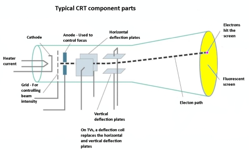
The cathode can be either directly or indirectly heated. If directly heated, the filament is the sole cathode. This arrangement is simple and works well in fluorescent bulbs, but in sensitive applications it introduces ac hum. An indirectly heated hot cathode consists of a separate metal cylinder that surrounds the filament and is negatively biased so as to repel electrons, which boil off the cathode, sending a relatively powerful stream of these particles on the brief journey to the screen.
Oscilloscopes have deflection plates as opposed to the deflection coils in TVs and computer monitors. Both work via the same principle – a beam of electrons deflects equally well when influenced by electrostatic or magnetic fields. TVs and computer monitors employ ramp-wave current in the deflection coils to move the electron beam horizontally, and at a slower rate vertically, so as to produce a raster on the screen. The intensity of the beam is varied to produce a full-tone picture, and beams from separate guns permit a color display. External circuitry blanks out the beam during the retrace so it won’t be a distraction.
As for the oscilloscope, two voltages are applied. To the vertical deflection plates is applied a fluctuating voltage that corresponds to the signal(s) applied to one or more analog channel inputs. To the horizontal deflection plates is applied the sweep voltage. A bright spot traces the waveform based on X-axis (time) and Y-axis (amplitude) calibrations. This works well except in the case of a repetitive signal, where the same location in the signal phase will not necessarily occur at a given point along the time axis. This causes multiple misaligned traces to appear so that a single coherent waveform doesn’t display.
The problem was overcome in 1946 when Tektronix introduced the Model 511 triggered sweep oscilloscope, which compares the vertical deflection signal or waveform amplitude level to a default or user defined threshold, which is the trigger level. Triggering is initiated when this threshold is crossed. The slope direction can also be selected.
Analog phosphor storage oscilloscopes differ from digital storage oscilloscopes, which store waveform events in solid-state memory. A conventional CRT used in an analog oscilloscope displays a waveform in real time, only as the event happens. One of the attributes of the phosphor applied during manufacture to the inside surface of the screen is its persistence. (Other attributes are brightness and color). Based on the type of phosphor, an image or waveform trace can persist from less than one microsecond to several seconds.
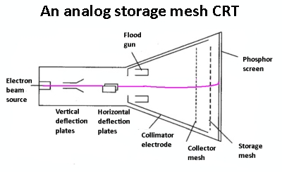
 To look at a short-duration transient event, a long persistence phosphor is preferable, whereas high-frequency signals display better in a short-persistence phosphor. In long-persistence phosphors, the image lasts only a few seconds. If longer image retention is desired, a storage tube holds the image until it is intentionally erased. It has a metal mesh bonded to a dielectric layer, located inside the tube adjacent to the phosphor layer. This grid is held at constant potential, and it is illuminated by a secondary electron beam from what is known as a flood gun. This beam is not subject to fluctuation because it does not pass between the deflection plates.
The primary electron gun produces an image in the phosphor layer and also affects the grid so electrons from the flood gun pass through, maintaining the current image on the screen until external voltage intentionally applied to the mesh obliterates any memory of that image. In actual practice, the image slowly fades anyway because the flood gun neutralizes the voltage pattern on the storage grid. Image retention can be boosted by temporarily turning off the flood gun.

Leave a Reply
You must be logged in to post a comment.