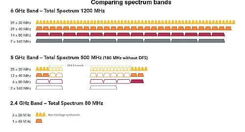
The 6 GHz band brings 1,200 MHz of additional spectrum to Wi-Fi which complicates the task of testing and verifying features.
Eve Danel, LitePoint
Now that the 6 GHz region of the spectrum is available for unlicensed use, Wi-Fi 6E devices are on their way to store shelves. Manufacturers face the juggling act of comprehensively testing these complicated devices while minimizing test time without compromising product quality.
There’s a difference between Wi-Fi design validation testing (DVT) and manufacturing testing. DVT encompasses all aspects of device performance and validates a broad list of items that truly push the design to its operating limits. By contrast, manufacturing testing aims to identify manufacturing defects or component tolerance issues that affect device performance; the calibrations and verifications performed on the manufacturing floor are only those necessary to ensure device quality.
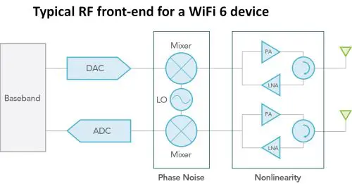
At the baseband/modem level, Wi-Fi 6E and Wi-Fi 6 are similar – both follow the 802.11ax standard. However, the Wi-Fi 6E RF front end (RFFE) requires components that cover a new and wide frequency range from 5.925 to 7.125 GHz. Manufacturing tests of Wi-Fi 6E devices must focus on the weakest links in the RFFE to identify performance issues.
In particular, active RF components that make up the front end can degrade performance. The 6 GHz band brings 1,200 MHz of additional spectrum to Wi-Fi (twice that of Wi-Fi 5 2.4 and 5 GHz bands combined). In the transmitter chain, the power amplifier (PA) must cover a wide bandwidth with high linearity. It must provide consistent gain even at the high edge of the band. At the highest channels, PAs with poor linearity will degrade the RF signal and, in turn, deliver poor signal range and coverage. Thus manufacturing tests must cover all channels in the 6-GHz band at maximum power to detect non-linearities.
The Unlicensed National Information Infrastructure (U-NII) radio band refers to the part of the spectrum used by 802.11a/n/ac/ax devices. The 6-GHz band (U-NII 5 to U-NII 8, 5.925 to 7.125 GHz) provides only a 75-MHz guard band for the highest Wi-Fi channel in the 5-GHz band (U-NII 3, 5.725-5.850 GHz), while the U-NII 4 band (5.850–5.925 GHz) reserved for dedicated short-range communications (DSRC) is only separated by a guard band of 25 MHz from the first channels in the 6-GHz band.
Stations or access points (APs) operating in the low 6-GHz band must comply with the tight out-of-band (OOB) emissions requirements imposed by regulatory bodies. These narrow guard bands make it challenging to transmit in the low-6-GHz band without leaking into neighboring bands and force the use of advanced filtering techniques.
Another approach used to meet these requirements is to back off from maximum transmit power in the first channel. Unfortunately, this approach sacrifices range on the first channels in the low-6-GHz band. The reduced range is especially problematic for the first 160-MHz channel (Channel 15) because some regulatory regions only provide enough unlicensed spectrum for three 160 MHz channels. To maximize transmit power, each device should be optimized during manufacturing for output power. This process, combined with spectral mask measurements, ensures a maximum transmit power without garbling emissions in adjacent channels.
Power level and RSSI accuracy
RSSI, or Received Signal Strength Indicator, is a measure of how well a device can obtain a signal from an access point or router. It’s basically a gauge of signal strength and determines if there is enough signal to get a good wireless connection. While not specific to Wi-Fi 6E, it poses a challenge tied to a feature introduced in the 802.11ax standard designed to improve capacity:
Orthogonal frequency division multiple access (OFDMA) is a multi-user version of OFDM where the Wi-Fi channel is divided among multiple users who simultaneously exchange data with the access point. When multiple users share the available spectrum, interference from a single bad actor can degrade network performance for everyone else. Client stations located at various distances must adjust their power based on their estimated path loss to the AP. Devices closer to the access point transmit with less power, while devices farther away transmit at higher levels to produce the same power level at the access-point receiver.

For uplink OFDMA transmissions, the 802.11ax standard requires stations to precisely measure the received signal strength indicator (RSSI) to evaluate path loss. In turn, stations must precisely adjust their transmit power to participate during the transmission. Class A devices must meet ±3 dB RSSI accuracy and ±3 dB transmit power accuracy.
Just as calibration during the manufacturing process ensures accurate transmit power, calibration of RSSI on the receive chain ensures accurate path loss measurement; the meeting of IEEE specs requires both RSSI and transmit power accuracy. Previously, RSSI was only used to determine the number of signal strength bars displayed on the user-interface screen–tight RSSI calibration was unnecessary. Now, RSSI is an integral part of how Wi-Fi 6 and Wi-Fi 6E work.
Beyond standard compliance, for the end user RSSI calibration provides the added benefit of a better roaming experience. It allows station devices to determine and choose the signal from the best AP more precisely.
High modulation: 1024 QAM or 4096 QAM
1024 QAM modulation is already part of Wi-Fi 6 in the 2.4 and 5 GHz bands, while the previous- generation 802.11ac (Wi-Fi 5) only supported up to 256-QAM. 4096 QAM is not part of the 802.11ax standard. However, some chipsets have started to include it as part of their Wi-Fi 6E offering. These modulations unlock the highest Wi-Fi data speeds thanks to 10 bits of data encoded per sub-carrier in 1024 QAM and 12 bits of data per sub-carrier in 4096 QAM. With high-order modulation, the constellation points are much more closely spaced, and devices become more sensitive to impairments. Thus the receiving radio requires a higher SNR to properly demodulate signals.

Obtaining the highest level of modulation accuracy for 1024 QAM and 4096 QAM forces the chipset and RF front end to have excellent phase noise and linearity performance. This accuracy is measured by the error vector magnitude (EVM). The 802.11ax standard requires below −35 dB EVM for 1024 QAM. 4096 QAM is not defined in the 802.11ax standard, however, its operation would require an EVM below -38 dB to deliver an equivalent signal quality. In manufacturing, EVM is measured because it provides an accurate picture of transmitter quality, and this metric will reflect any distortion in the transmit chain.
When measuring EVM, it is important to ensure the test equipment’s own EVM floor is 8 to 10 dB better than the device under test (DUT). This margin eliminates sources of uncertainty in the measurement and improves DUT yield performance.
Though 160-MHz channels were defined in the 802.11ac standard (Wi-Fi 5), they were often not supported or deployed because of the reduced spectrum that resulted in the 5-GHz band. The addition of the 6-GHz band opens enough contiguous spectrum to make full use of these wide channels. So expectations are they will be widely used in 6-GHz deployments.
Wider channels present design challenges because more bandwidth also means simultaneous transmission of more OFDMA data carriers. The 802.11ax standard boosted the number of subcarriers by four over the previous generation. Sub-carriers are now 78.125 kHz apart in 802.11ax, compared to 312.5 kHz spacing in 802.11ac. A 160-MHz channel is comprised of close to 2,000 sub-carriers. Distortions arise when the carriers at different frequencies are attenuated or amplified by different factors; the larger the range of frequencies, the more likely they are to exhibit this type of distortion.
Thus manufacturing tests must validate transmitter performance for 160 MHz channels. The spectral flatness is an excellent metric for this purpose as it measures the distribution of the power variations for all the sub-carriers of the OFDMA signal.
In a nutshell, the main goal for production test is to exercise the device as much as necessary to identify manufacturing defects while minimizing test time. An optimal production test focuses on areas exhibiting the largest degree of variability associated with the manufacturing process. For Wi-Fi 6E the primary challenge comes from the addition of a new and wide frequency range from 5.925 to 7.125 GHz. The test plan should include the following items to ensure complete coverage:
Low, mid and high 6-GHz band channel test coverage to verify consistent performance over the entire frequency band.
Transmit-power calibration and spectrum-mask measurements on 6-GHz channels to ensure meeting of regulatory emissions and optimization of transmit power.
RSSI calibration to ensure accuracy of path loss measurement for up-link OFDMA transmission.
EVM measurement for 1024 QAM (MCS10, MCS11) and 4096 QAM (MCS12, MCS13) (if supported by the chipset).
Test coverage for 160 MHz channels to ensure consistent performance.
For such high-level testing, test speed becomes the most efficient tool for controlling test costs. The test tool must be able to make use of advanced testing techniques combining multi-DUT parallel testing and test-command sequencing to reduce test time. These capabilities together yield greater test throughput for the next generation of Wi-Fi 6E devices.


Leave a Reply
You must be logged in to post a comment.