Conceptually, the interferometer is a relatively simple instrument that compares two distances typically differing only by a slight amount. Two waves, often coherent light waves, reflect from standard mirrors mounted at the object under investigation. The light from one mirror passes through a half-silvered mirror while the light from the other reflects from the back side of the same half-silvered mirror. Then the two beams travel to a detector.
If the two light paths from the coherent light source to the detector are precisely the same length, the light at the detector will be in phase, interfere constructively and strengthen in intensity. If the distances differ the slightest amount, the light beams will be out of phase, interfere destructively and weaken in intensity.
At the detector, any phase angle between the two beams can be determined by looking for a fringe associated with the combined, now single beam. What makes this technique work is the extremely high frequency (short wavelength) of light, so slight distances between the objects under investigation, corresponding to a small fraction of the light wavelength, result in significance phase differences in the two reflected light beams.
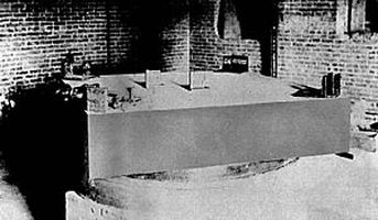
An improved 1887 apparatus occupied a massive stone basement. Michelson and Morley believed the masonry enclosure would both dampen vibrations caused by passing horse-drawn carriages and eliminate thermal effects. Moreover, the interferometer rested on a 5x5x1-ft sandstone slab, which floated on a pool of mercury. This arrangement permitted the interferometer to be turned so measurements could be taken at different angles to the earth’s absolute motion.
As the experimenters rotated the sandstone slab, one arm of the interferometer would align with the earth’s line of travel just as the other arm became perpendicular to it. With the hypothetical aether wind, the spectral signature should have been a sine wave with peaks corresponding to the alignment of the two interferometer arms with respect to the earth’s line of travel.
Of course, the experiment failed to detect the chromatic fringes that would indicate an aether wind. But one of its by products was the interferometer which, because of its great precision and simple implementation, eventually became a widely used investigative and spatial measuring technique. Applications range from astronomy to particle physics and micro-surface profiling.

In its simplest configuration, the Fabry-Perot device consists of two plane, parallel, highly reflecting surfaces separated by some distance. Thin silver or aluminum film typically comprises the reflecting surfaces. The air gap (called the cavity) generally varies from several millimeters to several centimeters. If the gap can be mechanically varied by moving one of the mirrors, you have an interferometer. A device with mirrors held fixed and adjusted for parallelism by screwing down on some kind of space is said to be an etalon.
A Fabry-Perot etalon operates by multiple beam interference. Light hitting the first reflection surface is split by reflection into a series of parallel transmitted rays. A ray is partially transmitted at each reflection from the second surface.
One confusing point is that there are numerous variations of the basic instrument. Fabrv-Perot interferometers, tunable etalons, confocal etalons, solid etalons, PZT scanning resonant cavity interferometers, fixed air gap etalons, pressure tuned Fabry-Perots, are all names for different versions. All are capable of extremely high spectral resolution, are extremely efficient (transmission can range up to 99%), and are spectrally tunable.
If the cavity is illuminated with a beam of coherent, monochromatic light, it will transmit the beam when the optical path length between the surfaces is an integral number of half, quarter or eighth wavelengths of the incident light. The fractional wavelength varies with the type of cavity used.
The interferometer can be tuned by moving one mirror with respect to the other, often via piezoelectric materials. Piezo elements may tilt the mirrors and change the pressure and thus the index of refraction of the air between the plates. Changing the temperature of the spacer elements used to separate the mirrors is another means of tuning.

Another example is the Keysight 10736A Three Axis Interferometer, used in multiple axis applications for linear and angular control of the stage. It combines the functions of an optical bench with multiple beam benders, beam splitters, and three interferometers. The interferometers split an incoming laser beam into three beams to measure linear distance, pitch and yaw, or linear distance, roll and yaw. Three linear measurements provide the basis for calculating two angular measurements. The inherent beam parallelism ensures that there is essentially no cosine error between the three measurements and also ensures angle accuracy for pitch and yaw measurements.
Interferometers have been used in a great many exacting applications. The laser interferometer as a means for detecting gravitational waves was first proposed by scientists in 1962 and prototypes including LIGO (Laser Interferometer Gravitational Wave Observatory) were built in the 1970s. LIGO detected the first gravitational waves in 2015 when two black holes collided.
The LIGO interferometer’s two lines are each 2.5 miles long. A 20-W laser beam undergoes power recycling by means of a dedicated mirror, which transmits light from the laser plus reflected light, boosting the power to 700 W. Partially silvered mirrors constitute cavities in the two arms, resulting in 100-kW light fields.
The object is to detect an alteration in space-time when a gravitational wave enters the interferometer. When this occurs, the length relative to one another of the two cavities changes, so the light beams become out of phase, resulting in a measurable signal. The beams make approximately 280 journeys through the 2.5-mile length to the far mirrors and back, whereupon they leave the arms and recombine at the beam splitter. Noise causes the optics to move, creating spurious gravitational wave signals, and the operators at the facility are constantly working to mitigate this noise. Gravitational waves from over 10 million light years from earth distort the 2.5-mile cavity less than 1/1,000 the diameter of a proton, but today’s most advanced interferometer nevertheless can detect it.


Leave a Reply
You must be logged in to post a comment.