Like a logic analyzer, a bus analyzer is capable of monitoring and capturing bus communication data. Both instruments decode, analyze and display that information. There are, however, significant differences. While a logic analyzer can display data from any of a large number of buses, an individual bus analyzer is built to work with only a single bus. Thus, there is an I2C bus analyzer, a MIL-STD-1553 bus analyzer, etc. As you might expect, a bus analyzer is generally less expensive, easier to operate and more portable than the larger bench-type logic analyzer. Within the scope of its single bus, the bus analyzer has considerably more
functionality compared to the multi-tasking logic analyzer.
When deciding which of these instruments to purchase, one must consider the nature of the planned work. Within a lab or facility examining many types of digital equipment, the obvious choice is the logic analyzer. On the other hand, at an aircraft manufacturer where MIL-STD-1553 Bus is used exclusively, the bus analyzer would have priority.
Two types of bus analyzers are currently available: the stand-alone or box analyzer and the computer-based bus analyzer. (The user supplies a desktop or laptop, or it may come with the analyzer as an integrated instrument.)
The box analyzer is notoriously difficult to use and a lengthy learning period is required before the operator can be considered truly adept. Complex bus traffic patterns combine with obscure controls and commands to create a challenging situation for new users.
The computer-based bus analyzer, in contrast, is far more user-friendly. It consists of a graphical user interface (GUI) that may be accessed via a Windows-based computer. In the GUI, the instrument displays data as message-based information, data shown in engineering units or as gauges and strip charts. Data can be exported to Microsoft Excel or displayed in other programs.
Abaco Systems has an advanced line of serial bus products including a turnkey product integrated with a ruggedized laptop. Additionally, they market a single-bus analyzer that works with AFDX, ARINC 429 and CAN Bus.
One of the functions that a bus analyzer performs is simulation. The analyzer generates data and injects it into the system under test. In this way, it can ascertain whether the system operation is valid with various inputs. The analyzer also introduces error signals into the bus so that responses can be observed and evaluated.
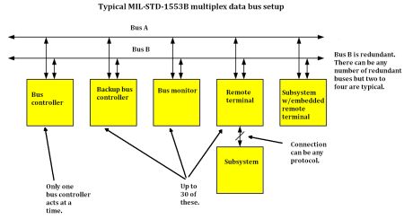
In MIL-STD-1553, the bus analyzer looks at the bus output while simulating sensor and sources.
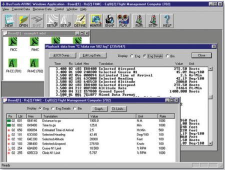
Another function is data display. Abaco System’s BusTools/1553 Analyzer lets the operator see an image of an aircraft with line-replaceable units superimposed. This facilitates maintenance operations down the road. The user can translate data to engineering units and display it in the form of gauges, indicators and charts resembling actual cockpit instrumentation.
 A third function is data logging and analysis as it pertains to development and integration in the avionics system. It is essential to determine whether line-replaceable units respond correctly when they see data with errors. Also, do line-replaceable units exhibit faults on the bus and is message content and scheduling appropriate?
A fourth function is data playback. In-flight activity can be recreated in the laboratory where it is viewed with the bus software and hardware.
Bus analyzer users often add a bus or protocol exerciser to the bench. The objective is to generate communication stacks that are compatible with the bus under investigation. Then bus traffic can be generated for design debugging. Also, purposely invalid bus traffic can be synthesized to test the device error-recovery systems. This is useful also for verifying compliance with the standard applicable to a specific bus. Exercisers can be stand-alone or combination units integrated into the bus analyzer.
Like bus analyzers, bus exercisers may take the form of computer boards, modules or portable units. Bus analyzers then check the protocol in real time, extract bus performance statistics, and monitor latencies, throughput and data transfers. Bus exercisers, in contrast, emulate and force bus behavior, so their operation may be considered active compared to that of the more passive bus analyzers. They intentionally disturb the bus and connected equipment by forcing errors while measuring the response of the system. Bus analyzers and bus exercisers work at definite speeds in regard to data capture rate and transfer rate, expressed in megabytes/s.
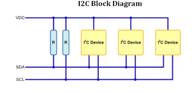 The I2C bus is made up of two signal lines and a common ground. The signals are conveyed on a serial data line and a serial clock line. A voltage, conditioned by a pull-up resistor, is imposed on each line. The devices are connected to the two lines and also to a power line. Each device has a unique address. Masters function as both receivers and transmitters.
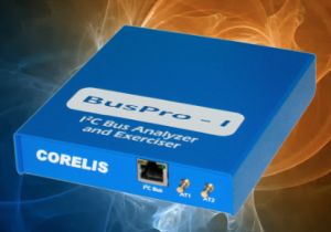
The Corelis BusPro-I is capable of monitoring and logging I2C traffic in real time, generating traffic to exercise the bus and communicate with its slave components as well as programming and reading the system’s EEPROMs. The product is designed for product development, troubleshooting, validation, system integration, production and field testing.
The BusPro-I connects to the user-owned PC via a USB port. It operates with the included I2C exerciser software, or using the included API C/C++ library of third-party software applications such as National Instruments’s LabWindows/CVI and LabView, or custom user-developed software.
The BusPro-I has a software toolset that consists of a monitor, debugger and programmer.
When the device is connected to an I2C bus, the monitor listens and records all I2C bus traffic while displaying it as both state and timing information, which can be stored in files and later retrieved for review. The monitor is capable of filtering, symbolic translation of numeric values and event triggering. The device continually verifies compliance with the bus protocol and it flags errors.
The debugger tool can send and receive individual messages on the I2C bus under test. Looping facilitates user observation of input-output patterns. Files of received data may be stored to perform post analysis and reuse previously sent message scripts. Third-party applications from an API library can be applied to the I2C bus for debugging operations.
The Corelis BusPro-I software programmer tool lets the user perform high-speed programming of I2C-compatible serial EEPROM memory devices with a user interface similar to the Corelis ScanExpress programming boundary-scan in-system programming product. In-system programming can be completed in just a few seconds. Included in the programmer are options to erase, program, verify and read the EEPROM memory. The memory content can be saved to a supported file format such as Motorola S-Record, Intel Hex or a hex-text file format.
To use the I2C bus exerciser, it is necessary first to install application software in the user-supplied PC. Then, the BusPro-I controller can be connected. The application software contains the driver for the BusPro-I. Because it is USB-connected, the controller is hot-pluggable. But the BusPro-I should not be plugged in or unplugged while the I2C Exerciser application is running. A furnished CD contains the installation program. The computer operating system will automatically recognize and configure BusPro-I the first time it is detected.
To install the software, close any Windows applications that are currently running including virus checking software. Then insert the CD and follow onscreen instructions as displayed in the I2C installation wizard.
After the software installation has been completed, BusPro-I hardware must be hooked up. To do this, connect a USB 2.0 or newer cable to the BusPro-I and to an available USB port on the PC. The driver will automatically install.
To finish, plug the RJ45 connector end of the target cable into the BusPro-I socket labeled serial bus. Connect the other end of the cable to the I2C bus that is to be investigated.
Without an I2C bus attached, the BusPro-I has a Demo mode, which allows the user to learn the many bus analysis features that are available in this instrument. Then, you can click on the Tools menu, uncheck Demo mode and switch into Live mode so that an actual I2C bus can be tested.


Leave a Reply
You must be logged in to post a comment.