How to test and maintain obsolete systems when the relevant documentation is absent.
Alan Lowne, Saelig Co. Inc.
Obsolete PCBs or boards lacking circuit schematic diagrams present a conundrum when there’s a need for repair. Online searches for old datasheets may not be productive. What happens when obsolete boards must be fixed but there is only one “golden board” left?
The scenario often arises in the military sector where equipment has a long operational life but the original manufacturer may be long gone, and the relevant documentation is unobtainable. The military must maintain its equipment no matter how long ago a product was designed and assembled. The ability to repair or replace legacy components is essential for military readiness, but it can also be costly.
When systems have an operational life of upwards of 25 years, the support strategy for spares and repairs is critical. Product support often evaporates when companies are taken over, restructured, or closed. Rapidly changing technology also makes support problematic. Consumer products, for example, often lose support long before the end of their operating life. But obsolescence is unacceptable for a product lacking a physically and functionally identical (form/fit/function) replacement that is also part of a validated system having a long life. A change to a new component in critical equipment such as military gear or medical diagnostic machines may be enormously costly and could require recertifying the whole system.
The need is for a system that will create essential product documentation available to all parties. Even better would be one that provides a schematic of the PCB under test and even creates a new PCB layout to enable the manufacture of new boards.
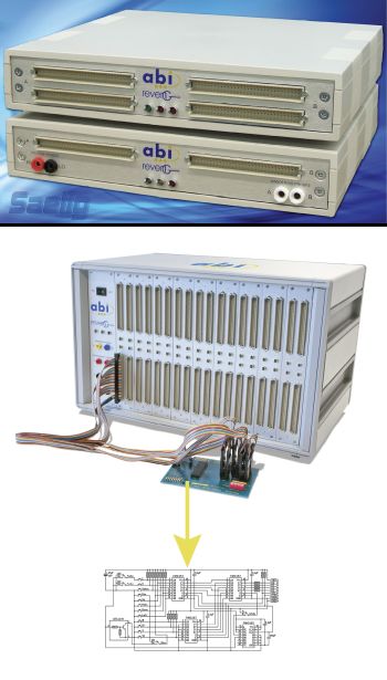
The typical way of re-documenting a PCB involves laborious, manual point-to-point circuit detection, observation, and notation. There is a better and easier way. A product from ABI Electronics (UK) called RevEng (REVerse ENGineering ) has been designed as a reverse-engineering hardware tool for recreating professional quality circuit schematic diagrams from a sample PCB lacking supportive documentation. The RevEng System consists of a PC-controlled continuity-detecting hardware system, control software called SYSTEM 8 Ultimate, and EdWin, a fully featured CAD package. RevEng ‘learns’ the connectivity of the sample circuit, producing a netlist of the components and connections which can be imported into either the EdWin software or into another schematic software package, producing professional quality circuit diagrams. New PCB layouts can also be created from these netlists using autorouting PCB layout software.

Learning in RevEng takes place using a selection of clips, connectors, and probes that are attached to clusters of components on the board DUT. SYSTEM 8 Ultimate software guides the operator to place and move the clips around the board. SYSTEM8 Ultimate generates an efficient sequence of clip combinations and movements to learn all possible connections, but the operator can override the automatic placement of the clips if necessary.
To minimize operator errors, the system applies an orientation check and pin check to confirm clip contact and position. RevEng completes its learning process without applying power to the board and limits the applied voltage and current from the probes so semiconductor gates don’t turn on – which also makes it safe to use on low-power technologies. The resulting net list can form an input to CAD packages and as data input for ATE programs.
SYSTEM 8 Ultimate software also provides links to CAD software. It is also possible to ‘learn’ part of the circuit so just an obsolete or non-working section of a board can be replaced. The use simply defines those components to be included in the drawing and follows the normal RevEng guided procedure. Part or all of the remainder of the circuit can be included later if needed. To ensure complete confidence, RevEng offers rescan and verification procedures.
A drawing package called EdWin comes with RevEng and enables quick generation of drawings by importing the net list and using an automated process to place components and signal routing. The resulting drawings can include bus structures and multi-page schematics. EdWin has features such as importing the netlist to place components, auto-routing signals, multi-page schematics, bus structure support, a library of over 12,000 devices, ‘rubber band’ and ‘rats nest’ functions, block move and rotate, etc. The component library includes discrete parts, analog and digital ICs, microprocessors, memories, and connectors – but new and custom devices can be easily added without necessarily knowing the function of the device or even which pins are inputs or outputs.
The CAD software can be enhanced to include artwork for a circuit board layout, design verification, and simulation. Optional capabilities include BOM, PCB layout, mix-mode simulation, arizona autorouter, thermal analyzer, EDSpice, EMC + signal integrity. Edwin’s special features enable same-day drawings of unknown, complex boards.
Low-budget or small-to-medium circuits can use an entry-level RevEng System with 256 measurement channels. Larger, more complex circuit needs can use a high-pin-count system equipped with up to 2,048 channel measurement channels.


Leave a Reply
You must be logged in to post a comment.