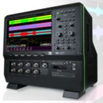
Prior to the digital revolution in electronic instrumentation, oscilloscopes displayed waveforms on cathode ray tube screens. Modern digital oscilloscopes universally have flat screens. The flat screen is light, thin, consumes far less energy, and is less expensive to manufacture. All agree that it is a great improvement. The one advantage of CRT technology is that it is easier to understand.
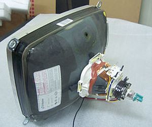
Sealed in a large, funnel-shaped glass envelope, the CRT as used in old-style TVs is of necessity fairly heavy because the glass envelope contains a vacuum. In the event of breakage, a substantial implosion sends glass shards flying everywhere. There are two reasons for the vacuum. The glowing filament, as in an incandescent light bulb, would burn out instantly in the presence of oxygen. And second, a vacuum is required for the beam of electrons, generated at the narrow end of the tube, to travel to the screen at the large end where a phosphor layer resides. The first CRTs had cold cathodes, but by the 1920s incandescent filaments were added. They heated the cathode, stimulating more intense electron emission.
This glowing filament heats the negatively biased cathode, which ejects electrons. This cloud of electrons is focussed into a narrow beam. Its intensity is modulated and it is directed toward the center of the screen. (For color, three such electron guns are required. Needless to say, the electrons are not different colors. The beams strike the screen at discrete angles, activating the appropriate phosphors.)
In a TV CRT, horizontal and vertical toroidal deflection coils on the outside of the neck cause the beam to scan the screen. As its intensity varies, the beam creates the moving images that viewers see.
An oscilloscope CRT is much smaller than a TV CRT because the screen is smaller and the electron beam does not travel as far. The oscilloscope CRT works in a similar fashion, but rather than coils, there are internal deflection plates, horizontal and vertical. These electrostatic deflection plates operate at a few thousand volts, much lower than the coils in a TV.

The horizontal deflection plates cause the spot made by the beam to move parallel to the horizontal X-axis at a user-determined rate in response to the horizontal scale knob. Depending upon the frequency of the signal to be displayed, the rate is some number of microseconds per division. (Most oscilloscopes have a time base made up of 10 horizontal divisions across the display.)
The vertical deflection plates cause the spot on the screen to move vertically parallel to the Y-axis in response to the rapidly changing signal amplitude. Thus, the spot, responding to vertical and horizontal deflection voltages, moves throughout the area of the display, drawing the trace.
Because of its lower cost and many user-friendly qualities, the flat screen has totally replaced the CRT in all applications. CRTs are no longer manufactured.
The flat screen display produces a similar end product, responding to time base and signal amplitude. But there is no electron gun or electron beam. Because of its low cost, ease on the eyes and great portability, oscilloscope manufacturers will probably not be looking at competing technologies.
For a few years, plasma panels were common. A plasma display is made up of two glass plates separated by a thin layer of neon or similar gas. The plates have parallel electrodes situated at right angles to one another. Applied voltage causes the gas to glow and thus the image is formed.
Like the CRT and for similar reasons, plasma panels have fallen out of favor, replaced in most applications by liquid crystal displays (LCDs). Liquid crystal seems like a contradiction in terms. After all, isn’t a crystal generally thought of as a transparent or translucent hard solid with flat geometric facets? But as we shall see, LCDs incorporate liquids that are crystal-like insofar as they polarize light and block polarized light in a highly organized way depending upon the applied voltage.
Many LCDs are backlit by LEDs. In fact, if your computer screen remains black, most likely the LEDs, power supply or connecting cable is faulted and this is a simple repair.
At the rear of an LCD oscilloscope or TV is the backlight, originally fluorescent but currently consisting of an array of LEDs, making up a more uniform light source that is also more energy efficient, with less heat to dissipate. Situated in front is a pair of polarizer plates containing closely spaced lines, originally engraved but now created by chemical means. Light from the LED array is polarized by the rear plate. Because the plates are installed so the lines are perpendicular to one another, without the liquid crystals the unit would be opaque and the screen would appear dark. The liquid crystals are contained by two additional layers inside the polarizer plates, which align the two ends in such a way that they have a 90° twist, causing the polarized light in each individual cell to twist, negating the effect of the polarizing plates.
Voltage applied to the crystals counteracts the effect of the alignment layers, causing the crystals to straighten out so the screen goes dark. All this happens individually at a pixel level, and that is what creates the display. There is no gun or vertical and horizontal displacement and scanning as in a CRT. Overall the flat screen, using LCD technology, compared to the CRT, is less expensive. And there is less shock and implosion hazard and less heat dissipation, so it is easy to see why flat screen has displaced CRT usage in oscilloscopes, computer monitors and TVs.
LCDs are volatile flat-screen devices. To retain an image, the display must be periodically refreshed. That is why in bad weather when reception in a satellite dish TV system is interrupted, the picture pixellates and becomes unintelligible. Non-volatile flat panel displays are bistable, so that images are retained throughout a powered-down interval.
Flat-panel displays were originally envisioned as substitutes for CRTs in radar installations. Besides TVs and computer monitors, LCDs are used in many applications including instrument panels and aircraft displays for pilots. The size range is enormous, from wrist watches, hand calculator and smartphones to huge outdoor signs. Additionally, they are common in DVD players and watches. The prices have dropped dramatically, especially in medium sizes such as wide-screen TV’s and large computer monitors, which are now affordable for home use.

Without LCD technology, the hand-held, battery-powered oscilloscope would not be a reality. Also, PC-based oscilloscopes and spectrum analyzers have become viable for field use in conjunction with flat-screen laptops.
What makes an LCD work is that varying amounts of voltage cause the liquid crystals to rotate different amounts so that the light is polarized at discrete angles. If polarized light is rotated with respect to a polarizing filter, its intensity after passing through that filter is modified. We can demonstrate this behavior very easily by removing the lenses from polarized sunglasses. Looking at a light source (not the sun!) through both lenses, its brightness will be seen to change as one lens is rotated with respect to the other. The first lens polarizes the light and the second lens blocks a portion of it. Polarizing glass was originally manufactured by engraving closely-spaced lines on it, but now this is done by chemical means.


Thanks for sharing this information with us. This comparision help us a lot for knowing which one is the good. Keep sharing