Despite their similar names, histograms and spectrograms are totally different ways of displaying a signal or function in a digital storage oscilloscope (DSO). Both are useful in organizing and analyzing electrical waveforms, but the type of information that is displayed and the conclusions that may be drawn from them are worlds apart. Histograms and spectrograms have been used extensively in digital processing and neither is specific to the oscilloscope.
First a few basics. A histogram basically depicts an estimate of the probability distribution of some variable. To construct a histogram, the range of possible variable values gets divided into a series of intervals called bins. The bins must be adjacent to each other and are often (but necessarily) of equal width. Then a count of how many values fall into each interval determines the height of each bin such that the height is proportional to the number of cases in each bin. A histogram may also be normalized to display “relative” frequencies. It then shows the proportion of cases that fall into each of several categories, with the sum of the heights equaling one.
In contrast, a spectrogram is a visual representation of the spectrum of frequencies found in a signal as they vary with time. Spectrograms of audio frequencies are sometimes called voiceprints or voicegrams. When the data is represented in a 3D plot the resulting depiction may be called a waterfall.
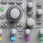
Today, most histograms and spectrograms involved in electrical engineering are constructed on oscilloscope displays. To see a typical histogram in the Tektronix MDO3000 Oscilloscope, first display a waveform (for example, the sine wave) from the internal arbitrary function generator (AFG). Then press the Measure button in the Wave Inspector section on

the front panel, followed by the soft key associated with Waveform Histograms in the horizontal menu. This brings up the vertical Waveform Histograms menu at the right side of the display. The top soft key permits the user to toggle Off, Vertical or Horizontal.
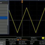
Choosing Vertical, with Source set correctly, we see the vertical histogram for the sine wave. The histogram with discrete bins appears to be situated horizontally but actually, the bins correspond to different amplitude levels on the vertical Y-axis. Least amplitude, where the sine wave intersects the X-axis, is represented by a shorter bar and greatest amplitude, where the waveform is farthest above or below the X-axis, is represented by the longest bar. Vertical histograms are good for measuring signal noise.
Horizontal histograms show the variation of elapsed time in the signal. Horizontal histograms are useful for revealing signal jitter. The rectangular box superimposed on the waveform designates the vertical and horizontal limits

within the waveform as represented by the histogram. Pressing the appropriate soft keys permits the user to set left and right horizontal limits and top and bottom vertical limits, using Multipurpose Knobs a and b.
In the horizontal Measure menu, the vertical Digital Voltmeter (DVM) menu can be brought up by pressing the appropriate soft key. Multipurpose Knob a chooses Off, AC and DC RMS, DC, AC RMS and Frequency. These values can be shown along with histograms.
Now to spectrograms. The Tektronix MDO3000 Oscilloscope can display a spectrogram by swinging the BNC cable over to the RF port, equipped with an RF adapter. With AFG and RF turned on, any of the AFG internal signals can be viewed in the frequency domain. (By pressing Freq/Span, Center Frequency and Span can be set so as to center the fundamental and display harmonics where present.)

The sine wave has no intrinsic harmonics because all the power is in the fundamental, but some appear in the display. They are probably introduced by the BNC cable and terminations. Such is the sensitivity of the instrument in RF mode.
In the RF menu, press the soft key associated with Spectrogram. The soft key toggles the spectrogram display On and Off. When it is activated, the spectrogram and frequency domain displays are shown in split-screen format. Both show frequency along the X-axis. In their Y-axes, they differ. The frequency domain plots amplitude (shown in power rather than volts as in the time domain) while in the spectrogram time is shown on the Y axis.
That is why when first turned on, the signal moves at a steady rate from the bottom to the top of the display. That leaves amplitude. Because a third Z-axis

cannot be shown on a two-dimensional surface perpendicular to the X- and Y-axes, engineers chose to use cool colors to depict low amplitude levels and warm colors to depict high amplitudes. The range of colors represents the range of amplitudes. Pressing AFG>Waveform and choosing square wave, one can see the more powerful odd harmonics and the less powerful (because they cancel out) even harmonics.
Where no signal is applied to the oscilloscope input or in regions of the spectrum where there is no fundamental or harmonic content, notice that the predominantly blue display appears to have a speckled appearance. That is the instrument’s noise floor. It is the same phenomenon that in the time domain display causes a slight thickening of the trace and in the frequency domain display shows up as an irregular fluctuating line near the bottom of the screen.

In an auto-ranging multimeter in the volts mode when the probes are not in contact with a live terminal or conductor, the display will appear to wander at a low level. Electricians call this “phantom voltage”, but it is actually the noise floor of the meter, caused by random thermal energy in the probes and in the conductors and components inside the instrument. When the probes touch a terminal or conductor that is live, the meter’s auto-range capability forces the instrument to go to a higher range so the noise floor disappears and the meter is said to “lock onto” the applied voltage.
Before the great digital revolution in oscilloscope technology, which happened in the 1980s, spectrograms could only be created using an array of band-pass filters. Now in a digital oscilloscope, the Fast Fourier Transform (FFT) is used.
A carbon microphone in series with a small dc power supply or an electret microphone can be connected to the RF port and a spectrogram of various sounds including the human voice can be created. Early types of speech synthesis were attempted with limited success by means of creating and transforming such images to sound. Similarly, spectrograms have aided researchers in analyzing various bird calls and other animal sounds.

Leave a Reply
You must be logged in to post a comment.