The terms spontaneous emission and stimulated emission sometimes get confused. The term thermal emission sometimes gets thrown into the mix as well. Here are the basic definitions to help sort things out and the procedures for measuring these parameters.
When we speak of spontaneous or stimulated emissions we are referring to atoms whose electrons are dropping from an excited state to a lower state, emitting a photon. Specifically, the electron emits a photon, then drops from an outer orbit to an inner orbit around the atomic nucleus. The mechanisms for how this happens are different in spontaneous and simulated cases.
Spontaneous emission is the mechanism responsible for most ordinary light. There are different names assigned to the phenomenon depending on how the atoms or molecules are excited. Spontaneous emission from atoms (or molecules) excited by some means other than heating is called luminescence. There are different forms of luminescence depending on how excited atoms are produced (electroluminescence, chemiluminescence, and so forth).
When the excitation involves the absorption of radiation, the spontaneous emission is fluorescence. You have phosphorescence when molecules have a metastable level and continue to fluoresce after the exciting radiation is removed.
The phase of the photon in spontaneous emission is random as is the direction in which the photon propagates.
The explanation of why spontaneous emission happens gets to be quite complicated. Physicists had to devise what’s called quantum field theory and quantum electrodynamics to show why spontaneous energy transitions can happen.
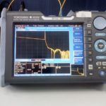
However, measuring the result of spontaneous emission is straightforward. Light meters — and more specifically, photodiodes — are the main tools for quantifying light emissions from ordinary sources.
Spontaneous emission leads to the definition of stimulated emission. Lasers start via spontaneous emission, then transition to continuous operation by stimulated emission. Stimulated emission refers to a process where an electron interacts with an incoming electromagnetic wave in the form of a photon. The electron drops to a lower energy level, but in so doing it transfers energy to the incoming field. This action creates a photon having the same phase, frequency, polarization, and direction of travel as the photons coming in. Thus the photon emission is stimulated by the action of another incoming photon.

For this action to happen a laser, there must be a condition called population inversion. In the absence of an external stimulus, there are always more atoms in low energy states than in higher ones. Although atomic absorption and emission of energy happen continuously, the statistical distribution (population) of atoms in the various energy states is constant. Pumping energy into the system alters this distribution to create a population inversion in which more atoms exist in the higher energy states than in the lower ones.
The mechanism for population inversion is the laser pump. In a laser, the optical cavity contains a gain medium excited by energy from the pump. It has a highly polished mirror at either end. Light bounces between the two mirrors to undergo amplification. The back mirror is 100% reflective while the front mirror is slightly less reflective. At each cycle a little light escapes through the less reflective mirror. But because the cycles recur with great frequency, the amount of emitted laser light may be quite substantial.

Measurements of laser output use several different technologies that depend on the power levels involved. Laser power meters can employ a thermopile detector, simply an array of thermocouples connected in series and close together. Thermopiles for laser power measurement use a temperature difference to create a voltage. On one side, the material heated by a laser (or any other radiation source), and on the other side is a heatsink. The voltage is proportional to the temperature difference between the two sides, which in turn is proportional to the laser power.
Laser power measurements can also employ ordinary photodiodes. Compared to thermopiles, photodiodes are faster, less affected by temperature fluctuations, and have lower noise levels. But their high sensitivity makes them susceptible to noise from ambient light. And they generally are compatible with lower power lasers.
Some laser power measurements use pyroelectric sensors which generate electrical current when subjected to changes in temperature. To measure power with a pyroelectric sensor, the signal must be chopped at a specific frequency so the instrument can convert the variations it detects into a power reading. One advantage of pyroelectric sensors is that they tend to work with lasers over a large frequency band.
Also available are integrating sphere detectors. Here, light enters a hollow sphere through a small aperture and diffuses inside the sphere to produce multiple reflections on the sphere’s inner coating. A small uniformly-lit aperture at another position in the sphere samples a portion of this diffused light and sends it onto a sensor. The point of this construction is that the integrating sphere acts as an attenuator to allow for the use of smaller and faster detectors with higher power lasers.
Finally, spontaneous and stimulated emissions can be contrasted with thermal emissions. Thermal emission, or thermal radiation, is the emission of electromagnetic waves and thus represents the conversion of thermal energy into electromagnetic energy. Thermal energy is really the kinetic energy of random movements of atoms and molecules in matter.
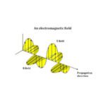
All matter with a temperature above absolute zero is composed of particles having kinetic energy. The protons and electrons in atoms and molecules have an electrical charge. Kinetic interactions among these particles result in charge acceleration and dipole oscillations. These oscillations generate coupled electric and magnetic fields. These fields result in the emission of photons.
The qualities of thermal radiation depend on the properties of the surface from which it comes. These properties include not just temperature, but also spectral absorptivity and spectral emissive power. And thermal radiation consists of numerous photon energies that make up the radiating body’s characteristic spectrum.
A radiating body that is in thermodynamic equilibrium with its surface and whose surface has perfect absorptivity at all wavelengths is called a black body. Thermal emissions of a body at any temperature takes place at a wide range of frequencies having a distribution given by Planck’s law of black body radiation. The dominant frequency range of the emitted radiation shifts to higher frequencies as the temperature of the emitter rises.

The simplest way to measure thermal emissions is with a thermometer. But industrial applications often involve nontrivial emission situations. So thermographic cameras are frequently used to gauge thermal emission details.
Thermographic cameras use the fact that the higher an object’s temperature, the more infrared radiation it emits as black-body radiation. A thermographic camera detects this radiation in a way analogous to ordinary cameras detecting visible light. A point to note is that the focusing lenses on a thermographic camera cannot be made of glass, as glass blocks long-wave infrared light. Typically the spectral range of thermal radiation starts at about 700 nm. So lenses must use special materials such as germanium, calcium fluoride, crystalline silicon or a special type of chalcogenide glasses.


Leave a Reply
You must be logged in to post a comment.