In setting up transmission lines, it is often desirable to measure the amount of signal reflection. The relevant metric is the standing wave ratio (SWR). SWR is defined as the ratio between the amplitude of a partial standing wave at antinodes [max] to the amplitude of the adjacent mode [min]. Thus a ratio of 1.5:1 means the maximum standing wave amplitude is 1.5 times greater than the minimum standing wave value. Voltage, current, and power can all be analyzed for reflections with the measurements being VSWR, ISWR, and PSWR respectively.
 An SWR meter is an inexpensive way to measure the SWR. To provide an accurate measurement of the ratio, the SWR meter must be designed to work with a specific characteristic impedance. Most SWR measurements are of coaxial cable having either 50 or 75-Ω characteristic impedance, the choice of SWR meter is simplified.
While the SWR meter quantifies the amplitude of a reflected signal, the time domain reflectometer (TDR) locates and characterizes the discontinuity or impedance mismatch. The instrument is connected to one end of the transmission line under investigation. It injects a pulse, and if there is a discontinuity or impedance mismatch somewhere on the line, the TDR receives the reflected pulse. Some TDRs inject a simple pulse. The width of the pulse determines the resolution of the measurement. But the downside of a narrow pulse is that it undergoes greater attenuation in a long cable run. Other TDRs use a half-sine wave.
The distance to the discontinuity is calculated from the elapsed time between the sent pulse and the echo. Also, by measuring the shape of the reflected pulse, the nature of the discontinuity can be determined. If the discontinuity represents an increase in impedance, the reflection will have the same sign as the applied pulse. If the discontinuity represents a decrease in impedance, the reflection will have the opposite sign.
The TDR is sensitive to impedance variations that are far too small to affect signal quality. Therefore, the instrument can be used to measure the distance to splices and connectors and to ascertain the cable length.
Though the SWR meter and TDR both involve reflected waveforms, they perform in quite different roles. It may be useful to contrast the operation of these two instruments.
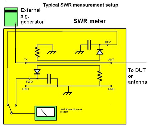
An SWR meter can consist of a directional coupler used to measure the magnitude of the forward and reflected waves by sensing each one individually. A calculation then produces the SWR. The signal generator is external and connects to transmitter terminals on the SWR meter. This connection is, in turn, connected to an internal transmission line and then to antenna (ANT) terminals. The forward and reverse waves get sensed via two smaller sense lines (directional couplers) typically terminated with resistors at one end and diode rectifiers at the other. The resistors match the characteristic impedance of the sense lines. The diodes convert the magnitudes of the forward and reverse waves to dc voltages which are then smoothed by capacitors and delivered to the SWR meter display.
Some SWR meters may use an impedance bridge to make measurements. The bridge is balanced (zero volts across the detector) only when the test impedance exactly matches the reference impedance. When a transmission line is mismatched (SWR > 1:1), its input impedance deviates from its characteristic impedance, allowing the bridge voltage to represent the presence or absence of a low SWR.
A point to note about SWR meters is they just read out a figure proportional to the amount of impedance mismatch. The actual impedance of any load is the sum of the reactance and resistance. To figure out the actual amount of reactance and resistance of the DUT, you need a network analyzer able to quantify S parameters.
A further point about SWR meters is that they typically find use in RF circuits and RF cables. This contrasts with TDR meters which are generally employed to find the location of problems in more general-purpose cabling. Though TDRs can be obtained as stand-alone instruments, their functions can be understood from an instrument setup 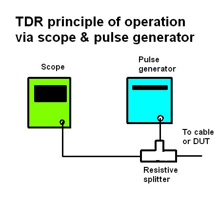 consisting of an oscilloscope and a pulse generator connected to a load via an ordinary T connector. The pulse generator emits a signal that both goes to the load and to the scope. The scope display shows both this emitted pulse and its reflection coming back from the load. The time between the initial pulse and the reflection is proportional to the distance from the TDR connection to the discontinuity.
When doing a TDR measurement this way, the human operator pretty much handles the calculations involved in computing the discontinuity distance. In stand-alone TDRs, a special delayed-sampling A/D converter does the calculation when given information about the type of cable being measured.
A point to note about TDR measurements is that they typically involve frequencies much lower than that of SWR meters. For example, a TDR pulse generator might put out pulses ranging from about 10 nsec to 5 μsec depending on the length of the cable being investigated. These pulse lengths have fundamental frequencies ranging from 50 Mhz to 100 kHz. Of course, the shorter the pulse length, the more precise the distance resolution.
Finally, similar instrument is the optical time-domain reflectometer (OTDR). The principle is the same. The instrument accepts optical fiber connectors, and it transmits and receives light pulses. Like electrical transmission lines, optical fiber may also have reflections, as when there is a dicontinuity in the transparent core. Discontinuities act like a mirror. Since single-mode optical fiber is often installed in long underground runs, the instrument is essential in verifying and maintaining fiber infrastructure.


Can you recommend me some swr meter? I’m looking for one but I don’t know clearly about it
what you think about Astatic PDC7 ? My friends recommend me it but I don’t know about it clearly