The thyristor is a two- or three-pin device comprised of four alternating P- and N- layers. It is also known as a silicon-controlled rectifier and is often used in light dimmer switches, speed controllers for electric motors, and switch gear for high-voltage dc power transmission systems.
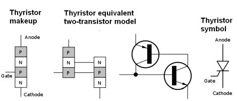 The thyristor does not function as an amplifier–its output is either on or off. It is essentially an externally-controlled rectifying diode. In contrast to the two-layer PN diode or three-layer NPN or PNP bipolar transistor, the thyristor has four layers (PNPN). The most common thyristor has three terminals designated anode, cathode and gate. In the three-terminal version of the thyristor, the four layers consist of alternate N- and P-type material. The anode is connected to the P-layer at one end and the cathode is connected to the N-layer at the other end. This configuration makes possible any of three possible states:
When negative voltage is applied to the anode and positive voltage is applied to the cathode, the thyristor functions simply as a reverse-biased diode and does not conduct. This is known as the reverse-blocking mode.
When positive voltage is applied to the anode and negative voltage is applied to the cathode, but there is no bias on the gate, the device does not conduct. This is known as the forward-blocking mode.
When positive voltage is applied to the anode and negative voltage is applied to the cathode and the device has been triggered into conduction, it will continue to conduct until the forward current drops below the holding current. (Thus, the thyristor is considered a latching device.)
If the positive (with respect to the cathode) voltage applied to the anode rises beyond a breakdown level in the manner of a Zener diode, avalanche occurs and conduction starts. This action happens at a lower level when positive voltage is applied to the gate. The speed at which the thyristor switches on depends upon the amount of voltage applied to the gate. Accordingly, there is a minimum gate voltage required to trigger the thyristor.
After the gate terminal has switched the thyristor on, the thyristor continues to conduct as long as it passes enough current. The latching current is the smallest amount of anode current necessary to keep the thyristor on at the instant the gate signal has switched the device on. The latching current is typically around two to three times that of holding current. Holding current is the smallest current under which anode current must drop to enter the off state. Thus if the holding current is 5 mA, the thyristor must pass less than 5 mA to discontinue conducting.
There are several other related devices whose operation is close to that of thyristors. Thyristors can only be turned on by applying a signal to the gate lead but cannot be turned off using the gate lead. In contrast, the GTO (gate turn-off thyristor) can be turned on by a gate signal and turned off by a gate signal of negative polarity. Turn-on is via a positive current pulse between the gate and cathode terminals. A static induction thyristor (SITH) is similar to a GTO but is normally on (conducting). The gate must be negatively biased to maintain the off state.
MOS-controlled thyristors (MCTs) operate something like GTO thyristors and have two MOSFETs of opposite conductivity types in their equivalent circuits. One handles turn-on, the other turn-off. A positive voltage on the gate with respect to the cathode turns on the thyristor. Negative voltage on the gate with respect to the anode turns off the thyristor. MCTs are hard to find. They were commercialized only briefly.
Silicon-controlled switch (SCS) or silicon-controlled rectifier, a variant of the thyristor. It is basically a thyristor with both an anode and cathode gate. This extra terminal allows more control over the device, mainly to turn off the thyristor while the main current through it is above the holding current value.
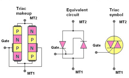 Triode thyristors (Triacs) work like thyristors but are bidirectional, passing current in either direction. Triacs can be triggered by either a positive or negative current applied to the gate electrode. Triacs can be visualized as two thyristors with gates connected. Like thyristors, triacs continue to conduct when gate current is interrupted. This state is maintained until the main current becomes less that the holding current.
A DVM can be helpful for verifying whether or not an thyristor is working. With the DVM set on a high resistance mode, connect the negative lead to the thyristor anode and the positive lead to the cathode. The resistance value should be high. A low value means the thyristor is shorted. Switching the leads and again reading resistance should produce another high value. A low value again implies a shorted thyristor.
With the DVM still connected to the thyristor anode and cathode, touch one end of a short jumper wire to the anode and simultaneously touch the other end of the jumper to the thyristor gate. If the thyristor is functional, the reading will be a low resistance. The value will remain low even if the jumper disconnects. In a properly working thyristor, if you disconnect either of the ohmmeter leads the resistance will return to a high value even when the lead is reconnected unless you short the anode to the gate again.
A point to note is that some thyristors work with only the amount of current supplied by an DVM set to the high resistance setting. If the thyristor can handle a larger current, try the R x 1,000 or the R x 100 setting.
The gate-cathode of an ideal thyristor is a PN junction. In many thyristors, there is also a parallel short-circuit path between gate and anode designed to pass a large initial current to help fire the thyristor. Because this path is made from uniform p-doped silicon, there is typically a measurable resistance of 10~50Ω between gate and cathode. However, manufacturers typically don’t characterize this resistance value. It’s given only to inform the user that a low gate-cathode resistance does not indicate a damaged device. When measured with the DMM diode check function, the gate-cathode connection will appear as a low (but nonzero) voltage drop (e.g. 0.01~0.05 V) in both directions.
A further point to note is that thyristors can give good DVM indications and still be defective. Ultimately, the only way to test an SCR is to subject it to a load current.
A DMM can also be used to test the health of a triac. Put the DMM in a high-resistance mode, then connect the positive lead to the MT1 terminal of the triac, the negative lead to the MT2 terminal. The DMM will show a high resistance reading. Now select a low resistance mode, connect the MT1 and gate to the positive lead and MT2 to the negative lead. The DMM should now show a low resistance reading (indicating the triac is on).
To summarize, for SCRs, the gate-to-cathode should test like a diode (which it is) on a DMM. The anode-to-cathode and gate-to-anode junctions should read open. For triacs, the gate-to-MT2 connection should test like a diode junction in both directions. MT1-to-MT2 and gate-to-MT1 junctions should read open.


Leave a Reply
You must be logged in to post a comment.