A few decades ago, virtually all computer monitors, radar installations, TVs and oscilloscopes employed cathode ray tubes for the user’s visual interface. Today, except for a few educational models and replacements for radar installations, CRTs aren’t used as displays. (CRT material and process technologies are still common in the vacuum tube industry as a whole where they find use in products such as incandescent, fluorescent, and high-power arc lamps; microwave, traveling wave, and high-power amplifier tubes, x-ray tubes, and magnetrons for heating.)
But it’s worth taking a close look at the CRT, particularly in the oscilloscope. Cathode rays were discovered in the late 19th century, right around the time James Clerk Maxwell found that light was a form of electromagnetic radiation. Generated within a vacuum tube, cathode rays cast shadows on the glass wall, indicating they traveled in straight lines. In 1890 it was found that cathode rays could be deflected by an electrostatic field and William Crookes demonstrated cathode ray deflection by magnetic fields.
The Crookes tube, developed in England in the 1870s, consisted of a glass envelope from which air was partially evacuated. The vacuum was necessary so electrons could travel unimpeded. Later when the hot cathode was introduced, the vacuum was additionally needed so the incandescent filament heating the cathode would not burn out. (The original Crookes tube was a cold-cathode device.) Numerous researchers investigated, wrote and lectured on the properties of these cathode rays. In 1897, J.J. Thompson identified them as streams of negative particles, later named “electrons.”
In the Crookes tube, electrons were generated by the ionization of low-pressure air surrounding the cathode. A dc voltage up to 100 kV was applied between the cathode and an anode at the far end of the tube. The resulting field accelerated electrically charged ions and electrons present in the residual gas. These energized particles collided with other gas molecules, freeing more electrons and converting the molecules to positive ions, which were attracted back toward the cathode. Upon impact, additional electrons were released, combining with and intensifying the beam.
The beam, traveling at approximately 20% of the speed of light, and many of the electrons flew past the anode, striking the tube’s end wall. They collided with atoms in the glass, knocking orbiting electrons into higher-energy shells. Falling back, these electrons emitted photons, a glow, visible outside the glass envelope. Next, researchers applied a phosphor coating to the inside of the glass wall, enhancing visibility and creating persistence. After striking the wall, the electrons returned to the anode, flew back through the attached conductor and power supply returning to the cathode.
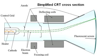
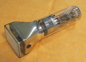
In 1895, Wilhelm Röntgen detected X-rays emanating from the Crookes tube, immediately suggesting medical and diagnostic applications. Around 1904, the Crookes tube evolved into a purely electronic vacuum tube in which a hot cathode, heated by an adjacent low-voltage filament, produced a stream of electrons by means of thermionic emission. Without the gas ions, this beam was more controllable, and in conjunction with a phosphor coating, all that remained to make a CRT for use in an oscilloscope were internal deflection plates and for TV, external deflection coils.
In TV and computer monitors, prior to the advent of flat-screen (mostly LCD) technology, the phosphor-coated inside of the CRT screen was scanned in a fixed pattern known as the raster. In color TV, an image is produced by varying the intensity, corresponding to video signal amplitude, of each of the three electron beams, which correspond to each of the primary colors. This makes possible subtle colors throughout the visual spectrum.

In an oscilloscope, electrostatic deflection is enabled by the Lorentz force, which acts upon any charged particle in an electromagnetic field. Electrostatic force works within an exclusively electrostatic, as opposed to magnetic, field and can also deflect a beam of electrons. The electrostatic field exerts a force on particles transverse to the direction of travel that is proportional to the strength of the field and to the charge on the particle. In an oscilloscope, the signal is applied to the vertical deflection plates. The Lorentz force varies with the instantaneous amplitude of the signal. A uniform time base is applied to the horizontal deflection plates. The result on the screen is a visual display of the waveform referenced to X and Y Cartesian coordinates.

Where long persistence was inadequate for displaying quick, non-repetitive signals, two types of direct-view storage CRTs were developed, phosphor-target tubes and transmission tubes. Both types contained conventional writing electron guns and flood-beam guns.
Under some circumstances, signals radiated from the electron guns, scanning circuitry, and associated wiring of a CRT can be captured remotely and used to reconstruct the CRT image using what’s called Van Eck Radiation. Here special equipment is used to pick up side-band electromagnetic emissions from the equipment, usually for the purpose of spying.
In 1985, Wim van Eck described the phenomenon and successfully eavesdropped on a real system hundreds of meters away using just $15 worth of equipment plus a TV set. Now, secure government installations take measures to prevent this kind of eavesdropping.
CRTs can become hazardous if dropped. Because a relatively large volume of air has been evacuated, the resulting implosion is intense. You might think the glass shards would fly inward, but in actuality, they fly out the other side and constitute a severe hazard to anyone nearby.
Additionally, CRTs use a high voltage to deflect and accelerate the electron beam. Touching exposed terminals and even insulated conductors can be lethal. Even when powered down and disconnected from the external power source, CRTs retain hazardous voltages for varying intervals depending upon the time constants of parallel-connected circuitry. Electrolytic capacitors are notorious for retaining charge, and there is also the matter of distributed capacitance. The CRT itself may harbor stored voltage, especially when removed from the cabinet and chassis with nothing to bleed it down.
Food and Drug Administration regulations in 21 CFR 1020.1 are applicable to CRT emissions. They limit CRT radiation exposure to 0.5 mR/hr at a distance of two inches. Most CRTs are in compliance. Because of toxins contained in older CRTs including cadmium and lead, the Environmental Protection Agency, beginning in 2001, required old CRTs be sent to e-waste recycling facilities as opposed to landfills or incineration.


Leave a Reply
You must be logged in to post a comment.