Ordinary conductors such as copper and silver exhibit less resistance as the temperature drops. But even near absolute zero they still have some resistance. With true superconductivity, the resistance of certain materials drops to precisely zero when they hit a certain critical cold temperature.
This type of superconductivity is a quantum mechanical process that involves nearly complete cancellation of the magnetic field that surrounds any conductor. The elimination of the magnetic field, internal or external, is due to the Meissner effect, the defining characteristic of superconductivity. The Meissner effect is defined as the expulsion of a magnetic field from a superconductor during its transition to the superconducting state. It does not entirely eliminate the magnetic field, which persists to a depth from the surface of typically 100 nm. This small dimension does not preclude superconductivity. It is known as the London penetration depth.
There are various modes of superconductivity and some of the exact mechanisms remain shrouded in mystery. In a conventional wire, electrons (the charge carriers) move across an ionic lattice. Electron-ion collisions convert electrical energy to heat. This action may be considered an energy loss because local entropy rises. It is the basis for electrical resistance.
In a superconductor, this loss is eliminated because the crystal lattice is not vibrating and the electrons do not collide with the ions in the lattice. It is like two baseballs traveling through space separated by a distance of three miles. Collisions are vanishingly infrequent.
The typical measurement made on superconductors gages the transition temperature, Tc. It’s tough to make this measurement on superconducting materials because most of them are a kind of ceramic, so there are difficulties forming them into thin wires or making electrical contact with them. Thus the usual approach to measuring Tc is to put the superconductor in an electromagnetic field, drop the temperature, and watch for the point where the material starts repelling EM waves, that is, the magnetic susceptibility around Tc.
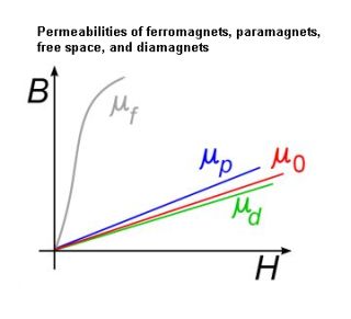
All materials develop a magnetic polarization in a magnetic field — they acquire a net magnetic dipole moment per unit volume often denoted by a vector magnetization M. The magnetization is often linearly proportional to the applied field H, so M = χH where the constant of proportionality χ is called the magnetic susceptibility. The magnetic field B inside the sample is
B = μ0(H + M) = μ0(1 + χ)H
where μ0 is the permeability of space. A superconductor cooled below Tc totally excludes the magnetic field, so χ = -1, several orders of magnitude larger than in a normal conductor.
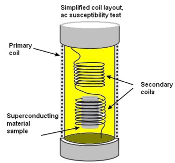 One typical way of detecting the susceptibility change is with a pair of (secondary) coils arranged in series that both sit inside and within the field of another primary coil. The superconducting sample sits inside one of these coils. A changing current in the primary produces an axial H field in both secondaries. The H field induces an ac voltage 90° out of phase with the driving current. The two secondary coils are identical and wound in opposite directions so the net induced voltage is close to zero. When the sample begins superconducting, it reduces the magnetic flux in one of the coils, making the whole apparatus unsymmetrical and producing a measurable signal.
The result can be summarized by the equation
v = KVfHχ
where v is the voltage measured out of phase with the driving current, V is the volume of the sample, and K is a geometric calibration factor specific to the instrumentation used. H is proportional to the magnitude of the driving current at frequency f. χ is small in the normal state, so the detected signal is effectively proportional to the volume fraction of the sample which has started to superconduct.
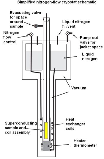 In the typical setup, the coils and the sample sit in a liquid nitrogen-cooled cryostat. The superconducting sample, coil, and temperature sensors generally mount to a rod through which the electrical connections route to the top of the cryostat. The cryostat interior can be evacuated or pressurized with dry nitrogen. The bottom part of the device holding the sample is generally surrounded by a copper heat exchanger through which liquid nitrogen flows. The whole system is insulated with a vacuum jacket and thermal radiation shields.


Leave a Reply
You must be logged in to post a comment.