An electrical conductor warms up when it conveys current. If the heat is high enough the conductor can be damaged, so it is beneficial to limit current flow. Three-phase electrical distribution systems are highly effective in limiting current flow without reducing the amount of power delivered to the load. They do this by separating phases and also by balancing the load. A circuit that is comprised of hot legs 120° out of phase with one another can deliver more power through smaller conductors.
Galileo Ferraris, Mikhail Dolivo-Dobrovolsky, Jonas Wenström, and Nikola Tesla in the 1880s independently invented poly-phase systems. Tesla conceived and developed the three-phase system and the three-phase induction motor.
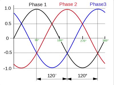
Three-phase power is usually generated in either of two configurations, Y or delta. The utility generator has three windings, arranged symmetrically so the current in each winding is separated by the same phase angle, one-third cycle, from the other two. This is 120° or 2π/3 radians. Outside the generator, the current from each winding can pass through one or a series of transformers, where the current and voltage, inversely related, are stepped up or stepped down without changing the phase spacing or frequency. At the customer end, a pole- or pad-mounted transformer converts the power to the preferred level and supplies it by means of three wires to the point of connection.
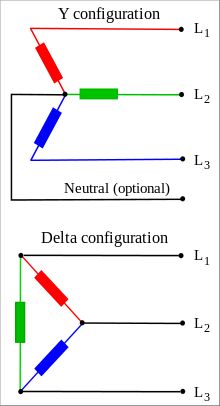
The more common Y-configuration connects one side of each winding to one of the three bus bars in the entrance panel and the other leg to a common, usually grounded, neutral bar. At the entrance panel, three-phase breakers clamp onto the three bus bars to supply three-phase loads and single-pole breakers clamp onto just one of the bus bars to supply single-phase loads. Thus, three-phase and single-phase power can be derived from a single entrance panel or load center without benefit of a transformer or phase converter, rotary or electronic. Where phase-to-phase loads are to be supplied, double-pole breakers are used.
A delta- (named for the Greek letter Delta, Δ) connected transformer winding is connected between two primary phases. In an open delta system, only two transformers are used while in a closed delta system, there are three transformers, one for each phase. If one of the transformers fails or needs to be removed, the system will continue to function as an open delta system at 58% capacity.
From the point of view of an electrician running wiring from a three-phase box, a double-pole breaker will pick up the voltage between two phases. A single-pole breaker will pick up the voltage at one phase in conjunction with a neutral bar conductor. In either event, an equipment-grounding conductor should also be run to facilitate over-current operation.
Some delta systems have a ground connection made at the midpoint between two of the three phases. These are called “center grounded” three-phase delta systems. Because of this center tap, one of the three phases will have a higher voltage with respect to ground than the other two. Care must be taken regarding this high leg. It is color-coded orange to distinguish it from the other two legs.
A three-phase motor is smaller, less expensive and lasts longer than a single-phase motor of the same horsepower because it is vibration free and is required to dissipate less heat. For this reason, most induction motors over five horsepower are three-phase, although fractional horsepower three-phase motors are also available. They are easy to wire. Just run the three supply conductors, with over-current protection at the correct ampacity, to the motor and terminate them at the motor. Use a motor controller if required.
To reverse rotation, interchange two of the three lines. Some motor loads, such as fans or pumps, operate more efficiently running in one direction than the other. The blade or impeller shape is the reason. Correct rotation can be determined by trial and error, measuring the output. However, some pumps are instantly damaged by incorrect rotation.
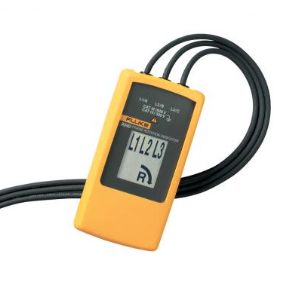
In a three-phase Y system or delta system without a grounded center tap in one of the windings, single-phase loads may be connected from a phase to neutral or across any two phases. This makes possible numerous single-phase voltages that can be used in various applications. If these loads are balanced, i.e. have equal impedance, transformers and conductors are used most economically.
In a balanced Y system, all three phase conductors have the same current and voltage with respect to the system neutral. With linear loads the measured voltage between line conductor when the loads are equal is the square root of three times the phase-to-neutral voltage.
A problem today is that an ever-increasing portion of connected loads are nonlinear. Ballasted fluorescent lighting, which is abundant in office settings, as well as switching power supplies and induction motors are examples of non-linear loads. They produce costly third-order harmonics, which are in-phase in all three legs. As a result, they are additive in neutral conductors. This excess loading causes neutral heating in branch circuits and distribution lines all the way upstream including within utility generators.
Single-phase electronic loads generate harmonics at all multiples of the fundamental. The most harmful of these are triplen harmonics, because their amplitudes are highest. Higher-order harmonics diminish in amplitude as they become more remote from the fundamental as represented on the X-axis in an oscilloscope’s frequency domain.
Three-phase loads do not generate triplen harmonics. Consequently, in industrial facilities with heavy three-phase loading, the greatest problem results from higher level odd harmonics — fifth, seventh, eleventh and so on.
Active filters can mitigate harmonics, but they are complex and expensive to implement. They digitally synthesize reactive power to cancel the harmonics. A more economical solution is to use phase-shifting transformers to attenuate the harmonics. They work by combining harmonics from different sources that are phase-shifted with respect to one another so the harmonics then cancel out. Other harmonic mitigation techniques include the use of line reactors, harmonic traps, 12- and 18-pulse rectifiers and low-pass filters.
Harmonics are also costly because they cause the apparent power in a system to exceed and stress the active and reactive components. Moreover, because they are higher frequency than the fundamental, harmonics reduce capacitive reactance, a parallel phenomenon, to a certain degree shunting out the intended load and heating up the supply wiring. In the presence of harmonics, capacitors see higher applied voltage, which can cause dielectric loss and actual damage. Three-phase induction motors also undergo loss and heating in their windings. Harmonics boost current and overheating in neutral conductors, which generally do not have over-current protection.
When large motors are not loaded to their full capacity, the cumulative effect within a facility is added to the presence of harmonics to reduce the power factor. Electric utilities frequently charge industrial customers a higher rate when power factor dips below 90%.
Power factor can be improved by adding power-factor-correction capacitors to the electrical system. A common implementation includes an automatic switch that places the capacitors on line only as needed.
Power factor correction capacitors require periodic inspection and maintenance. Thermal imaging is a good way to start. Workers should beware that these devices are capable of storing lethal voltages long after they are powered down. Arc flash is a potential hazard as well. In that regard, anyone who works with test instruments in close proximity to three-phase power circuitry should wear personal protective equipment (PPE) as dictated by safety standards.
There are also a couple of subtleties to be aware of when measuring three-phase electrical parameters. One concerns 480Y three-phase service. This configuration uses four wires, three hots, a neutral, and a ground wire. The voltage between any one leg and ground will be 277 V, and between any two hot wires you will measure 480 V. A transformer must be used to handle 120/208 single and three-phase loads. The transformer must have a 480Y primary and a 208Y secondary.
Three-phase machinery typically runs from Delta voltage, a configuration using three hot wires and no neutral wire. If a 230-V machine is mistakenly connected to 480 V, its motor will most likely burn up. Voltage does not affect the RPM of a motor, but the frequency of the voltage does.
Finally, there are different ways of measuring three-phase power. Perhaps the simplest is to use a single power meter to measure the power in one phase at a time. The potential problem with this method is that it assumes the power in the unmeasured phases is the same as what’s measured once the power meter is introduced in that phase.
The most straightforward method is to use a power meter in each phase leg simultaneously. Here, phase voltage for the power measurement is measured with respect to the neutral wire. Obviously, the total power is the sum of their readings.
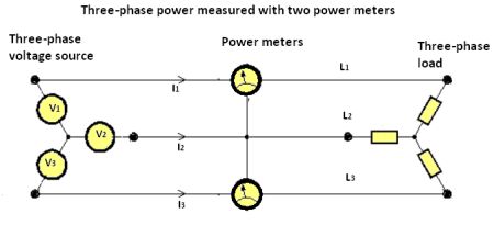 Interestingly, there is a way to measure three-phase power accurately with only two power meters. One of the phases serves as the null reference and the power need only be measured for the remaining two phases.
But there is a comparative calculation associated with this method that is employed as a check of its accuracy. It is easy to understand when the voltage source and load are in a Y configuration. Because the neutral isn’t connected, the sum of the instantaneous current in the three phases must be zero by Kirchhoff’s current law: I1 + I2 + I3 = 0.
It can then be demonstrated that the sum of the instantaneous powers of the three phases is equal to the instantaneous powers of two phases with the third phase (L2) as voltage reference:
V1×I1 + V2×I2 + V3×I3 = [(V1 – V2) × I1 ]+ [(V3 – V2)×I3]



Please note that the two meter power measurement method is accurate if there are NO SINGLE PHASE loads. The diagram in this article shows wye configured transformer and load without a neutral connection between them.
For wye connected loads with a neutral, the three meter method is required.
In an ungrounded electrical system (shipboard), does line starting 3-phase motors produce large harmonics?