The dominant oscilloscope type today is digital. A relatively small number of analog oscilloscopes are still made for educational purposes and low-end DIY kits. The digital revolution in oscilloscope design, initiated by Walter LeCroy over 50 years ago, made possible vast new capabilities and features. Still, it is worthwhile for perspective to look back at the old analog scope in order to get an overview of the basics. These two instrumentation subspecies have much in common, beginning with probing.
If possible it is best to connect a signal to an oscilloscope input via a BNC cable. This method is convenient and works well when the signal source is hardware-compatible. An example is connecting a synthesized signal from an internal or external arbitrary waveform generator to an oscilloscope input.

Often, however, the source of the signal is a trace or component pin on a printed circuit board, or a device terminal or wire in electrical equipment. In these situations, probes are essential. The most-used oscilloscope probe attenuates the signal by a factor of 10. It is known as a 10:1 or 10X probe. This probe is appropriate for most applications. Its resistive (dc) impedance, 1 MΩ, makes the oscilloscope-probe combination invisible to the circuit, component or network. So at moderate frequencies, loading is not an issue.
But parallel capacitive loading can be problematic when the signal under investigation is high frequency. This is inevitable when you consider the probe with cabling together with circuitry within the oscilloscope. Probe input capacitance, seen by the circuit under test, is typically 100 pF. When looking at a 60-Hz sine wave or any audio frequency, the capacitive reactance is not significant, but even in the low megahertz range, you may be down to a couple hundred ohms of capacitive reactance. The will cause some circuits to oscillate, rendering measurements invalid or actually damaging the circuitry.
Without upgrading to a low-capacitance probe, a good practice is to carefully compensate the probe. Each probe must be compensated to its channel, and it should be color-coded so the dedicated probe is always paired with its correct channel.

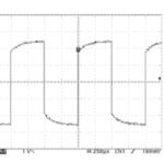
To perform probe compensation, oscilloscopes are equipped with external terminals that provide a square-wave signal. Turning a knob or screw on the probe body, the user compensates the probe so that a well-formed square wave is seen in the display, without overshoot or rounded corners. The Tektronix TPP1000 probe works somewhat differently in conjunction with an MDO 3000 series oscilloscope. The user clips onto the square-wave terminals and chooses menu items, whereupon the instrument automatically performs the compensation. Each channel can store compensation values for 10 individual probes. If you try to compensate an 11th probe on a channel, the oscilloscope will delete the values for the least recently used probe and add the values for the new probe.
To view low-amplitude signals, 1:1 (1X) attenuation probes are needed. (Some probes have a slide switch on the probe body that toggles between the two attenuations.) To view high-voltage signals, specialized high-voltage probes are used. They incorporate guarding that protects the user from shock.

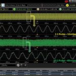
Differential probes are used to display voltage oscillations between two terminals when both are referenced to, but float above, ground level of the ac electrical system that powers the instrument. Differential probes are necessary in this instance because connections via a standard probe with a ground-return lead will create a direct short through both the circuit under test, the ground return lead and the oscilloscope, with possible severe damage. This can happen even if the oscilloscope is powered down and only the ground return lead is connected. Differential probes have an additional advantage which is that they reject any common-mode voltage, signal or noise. This feature can be useful in that it cleans up the desired signal so that accurate measurements can be made.
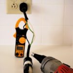
Current probes are expensive, but they enable new oscilloscope uses. In the Math mode, current and voltage waveforms can be multiplied to display power, with implications that are interesting and useful. The oscilloscope current probe works like the electrician’s clamp-on ammeter. Rather than cutting into a conductor (with eventual resoldering) the current probe clamps around the wire with no direct electrical connection. The magnetic field surrounding the current-carrying wire induces a voltage in the probe that displays on the oscilloscope with divisions calibrated to show amps or milliamps. To detect extremely low currents, the wire can be coiled and made to pass through the jaws two or more times. The displayed current is then divided by the number of turns to calculate the actual current flowing through the conductor.
The most common problem in using an oscilloscope is failing to get a signal to display in a meaningful way, or to display at all. Here are some strategies:
• Press default settings. This will clear the slate, so to speak. It is possible that in a previous work session the instrument was configured in a way that is not compatible with the current operation. Some of these configurations persist through successive power cycles. Some of them go away when the oscilloscope is turned off. Most of the time, pressing Default Settings takes care of this problem.
• Press Autoset. The instrument then analyzes the signal and automatically chooses the optimum settings in terms of frequency, amplitude, and scaling.
• Verify there is a signal at the oscilloscope input. Measure it with another oscilloscope or with a multimeter.
• See if another signal, from a different source, will display. The square-wave probe compensation signal is a good source, but be aware that in a Tektronix oscilloscope, the square wave is present at the terminals only momentarily as the probe compensation takes place. Try different channels with different probes.
• If the problem has been found to be within the oscilloscope, download the latest firmware, which is free at the manufacturer’s website.
Oscilloscope manufacturer websites are great resources. Perusing the available products with specifications, prospective users quickly acquire an overview of oscilloscope instrumentation currently available. Some websites provide pricing. Others want you to register, give your email and create a password with all that entails. You have to consider the long-term benefits and decide if it is doable.
Once into the site, you can access a great many application notes, register for webinars, etc., essentially allowing the manufacturers to send you to graduate school to study this specialized equipment.
Choosing an oscilloscope is, of course, a delightful pastime. The downside is that pricing for this laboratory grade instrumentation can be in the stratosphere. Most of us are compelled to compromise in some areas. We all enjoy high bandwidth and four (or more) channels though most of the time two will suffice.
The ultimate way to economize is to be content with a two-channel, 50-MHz PC-based oscilloscope. This solution is vastly less expensive than the venerable bench-type scope. But there are some disadvantages in terms of connectivity between the oscilloscope module and the owner-supplied PC with proprietary software installed. What is impressive, however, is the extensive functionality and advanced features that reside in the PC once the software is installed and the owner is up to speed.

Oscilloscope technology has come a long way since the post-WWII years when consumer electronics expanded rapidly until a TV and stereo sat in every home. These old tube-type machines were eminently repairable. Technicians injected signals into various stages and looked at the waveforms downstream. This procedure allowed them to zero in on the defective component(s) which could be easily replaced in the spacious chassis.
Now it’s a different world. Ultra-compact printed circuit boards populated with numerous ICs having multiple leads are difficult to replace and the circuitry is highly complex. The oscilloscope has evolved, becoming more of a developmental instrument rather than a repair tool.
The oscilloscope is our window on the universe. Consider the cardiac monitor: it saves lives and suggests new approaches to old problems. Healthcare technology is overwhelmingly concerned with imaging in one form or another, and the oscilloscope, not to mention its coworker, the spectrum analyzer, is a cutting-edge participant in the most advanced human endeavors you could imagine.


Hi David, nice piece! Scopes have come a long way, as you say. I’m with Rohde & Schwarz so I’m naturally biased toward benchtop equipment, particularly, in my case, for scopes and spectrum analyzers.
I agree that prices for dedicated equipment (vs PC based) can get pretty steep, per your statement, “The downside is that pricing for this laboratory grade instrumentation can be in the stratosphere.”
However, almost all of the major manufacturers have come out with oscilloscopes that offer enormous “bang for the buck”. The Rohde & Schwarz RTC1000 Series, for example, starts at $975 for a two-channel scope with a bandwidth of 50 MHz.
In addition to “laboratory grade” analog specs, you can outfit the scope with a number of options, including eight digital channels and serial protocol analysis. This mixed-signal capability makes it a good choice for designing and debugging microcontroller systems that have analog inputs and outputs. The key here is that the scope is flexible enough to meet a wide variety of applications.
High quality never gets old, but I have to say from experience, that using a laptop for regular test and measurement use gets old – very quickly. From my own experience, it was a space and time sink, especially considering what we can get on the market now, from R&S and other suppliers.
Best regards,
Rohde_TestWalker