We speak of 50- or 75-Ω coaxial cable. The novice wonders if these numbers apply to a given length, say 100 ft. Could you connect an ohmmeter to one end of the cable and expect to get that reading with or without the conductors shunted at the far end? The answer is absolutely not.
The characteristic impedance of coaxial cable or any type of transmission line is constant, regardless of its length. This metric is expressed in ohms but cannot be measured by an ohmmeter. The measurement takes a time domain reflectometer, some models costing thousands of dollars. An oscilloscope can also be used to ascertain this value. But it’s usually unnecessary to make this measurement on short lengths of coaxial cable; coax is manufactured to exacting specifications and labeled accordingly.
The discussion that follows presupposes the reader understands that impedance is composed of resistance and capacitive or inductive reactance, calculated vectorially. It also presupposes the reader understands that there’s a maximum transfer of power when the source and load match, i.e. their impedances are the same.
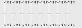
To understand characteristic impedance, we must visualize a transmission line of infinite length. As apparent in the accompanying diagram, the transmission line may be modeled as consisting of an infinite number of capacitances. This is entirely realistic because in coaxial cable the two conductors are the plates of a capacitor and the dielectric layer is the insulating material separating them. Similarly, conductors have a certain specific inductance per unit length. In this thought experiment we shall disregard the dc resistance of the wires, imagining they are cooled to close to absolute zero and have become superconductors.
When voltage is applied at the input of this infinitely long transmission line, the capacitors charge, a process that progresses down the line close to the speed of light. Each parallel-connected capacitor charges, dropping the applied voltage by a slight amount during the charging process. On an infinitely long cable, there are an infinite number of capacitors to charge down the line. Simultaneously, the series-connected inductors representing the cable diminish the current as they establish magnetic fields about them. As each magnetic field becomes fully established, the inductance no longer opposes the flow of current, but there are always more inductors downstream on an infinitely long cable.
Recall from Ohm’s law , R= E/I where R = resistance, Ω; E = electromotive force, V; I = current, A. In this infinitely long idealized transmission line, the ratio of E over I remains constant for any particular uniform cable. R also remains constant, and this is the characteristic impedance.
Novices sometimes find it difficult to understand what this infinite transmission line has to do with anything in the real world. We have had to stipulate that the line is infinitely long so there are no reflections from a non-existent end. Such reflections would bounce back to the source and change the cable impedance so it would not be uniform. Suppose there is a load at the far end of the cable whose impedance matches the characteristic impedance of the transmission line. Then regardless of the transmission line length, there will be no reflections. Without reflections, the source has no way to know that the line is not infinite.
Characteristic impedance becomes important at high frequencies. It must be considered in the design of point-to-point wiring, printed circuit board traces, and even inside semiconductor devices including microchips.
Now consider a probe connected to a particular oscilloscope channel. The probe constitutes a transmission line, and the scope input channel is the load. That is why the probe must be compensated to the channel. An impedance mismatch shows up as distortion in the very fast rise and fall times of a square wave, even at moderate frequencies.


very good thanks
I’ve been searching the web for a comprehensible explanation of characteristic impedance of coaxial cables, and this is the only useful and clear explanation I’ve found. Thank you!
But how to explain that the characteristic impedance should become sqrt(L/C),not (L/C)