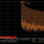
In measuring or displaying weak signals, noise places the ultimate limit on detectability. It usually appears as a fluctuating horizontal line known as the noise floor in a spectrum analyzer of oscilloscope in FFT or RF mode. In the time domain, it appears as a thickening of the trace and in severe instances, causes a loss of triggering. In the multimeter it is phantom voltage, puzzling to novices. It causes voltage in the readout, when there is no input, to wander. We see it as snow in video and hear it as odd sounds in audio. Everywhere, it is a broad-spectrum phenomenon variously known as thermal, Johnson, Nyquist or white noise.
Electrical noise is a natural consequence of the random motion of free electrons and ions in any conductor at a temperature that is not at absolute zero on the Kelvin scale. The noise floor in instrumentation should not be seen as a design or manufacturing defect. It is a mark of the great sensitivity of the instrument. Ordinary wire segments, circuit board traces, resistors, inductors, capacitors and all solid-components exhibit thermal noise. Any free-standing resistor will display a small but measurable voltage across its terminals unless shunted by connecting the leads, in which case there is a small but measurable electrical current between the leads. In all cases, this is an extremely low-level quasi-ac current, by which is meant a non-periodic fluctuating current that reverses polarity at random intervals. This action resembles the energy that we measure at the output of a solar cell, except that because the solar cell is a diode, the current is dc. Also, it is more intense due to incident solar radiation.
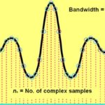
Open-circuit noise conforms to Vn = (4kTRB)1/2 where Vn = open-circuit noise in volts; T = temperature in degrees Kelvin; R = resistance in ohms; k = Boltzmann’s constant; and B = Bandwidth in Hz.
To put this in perspective, a 10KΩ resistor at room temperature has an open-circuit voltage of 1.3 μV at 10 kHz bandwidth. That’s just over a millionth of a volt! At any instant, thermal noise voltage is indeterminate, but it conforms to a Gaussian amplitude distribution.
There are multiple methods of mitigating thermal noise, such as cooling, bandwidth limiting and signal averaging. Thermal noise is generated internally, within the measuring instrument, within equipment being investigated and within the probe and cabling conveying the signal to instrumentation inputs.
Besides thermal noise, there are numerous other external noise sources in the vicinity of the measuring instrument or communicated over the powerline. These types of noise have distinctive characteristics:
• Electronic shot noise is the consequence of random fluctuations in electrical current when electrons or other charge carriers move across a barrier. Because electrons are discrete, their arrival causes shot noise, which has been likened to raindrops striking a tin roof. The value of shot-noise current is i = √(2Iq ΔB) where I = dc current; i = shot noise current; q = charge of one electron; ΔB = Bandwidth in Hz. Shot noise is not exhibited in conductors and resistors because internal heat generation smooths out the effect of the charge carriers’ discrete arrival times.
• Flicker noise, also known as 1/f or pink noise, is a low-frequency phenomenon, usually characterized by a Gaussian distribution. In resistors and FETs it is linear, while in BJTs and diodes it is non-linear. In carbon and thick-film resistors, flicker is called excess noise because it is higher in amplitude than thermal noise. It can be reduced by using wire-wound resistors. Another way to mitigate it is to minimize the dc component. Then, thermal noise is a higher fractional component and because it is wide-spectrum, it can be reduced by bandwidth-limiting techniques.

• Transit-time noise occurs within a transistor when the time for an electrical pulse is close to the period of the amplified signal. This causes the transistor to offer reduced impedance to noise. The phenomenon is increasingly apparent at higher frequencies.

• Atmospheric noise is caused by lightning or other natural electrical activity that is within range. Additionally, fluorescent lighting, high-tension wires, switchgear, electric motors (especially with brushes) and automotive ignitions contribute to the electrical noise environment. Solar noise comes and goes. Examples are corona discharges and sunspots.
Noise mitigation is absolutely necessary when working with low-amplitude signals. As for thermal noise, the principle mitigation techniques are bandwidth limiting and signal averaging. Because thermal noise is a broad-spectrum phenomenon, it can usually be reduced by means of bandwidth limiting. Modern digital storage oscilloscopes invariably perform this function. In the Tektronix MDO3000 Series Oscilloscope, for example, press the channel button to bring up the horizontal channel menu. Then press the soft key associated with Bandwidth to bring up the vertical Bandwidth menu. Soft keys permit the user to limit the bandwidth to 250 MHz and 20 MHz. Limiting the bandwidth to 250 MHz eliminates a portion of the noise and limiting it to 20 MHZ is still more effective. A problem in this noise mitigation technique, however, is that often the full bandwidth is required to display the signal of interest.
The other noise mitigation technique is signal averaging. To see how it works, first press the Acquire button. Then, in the horizontal menu, press the soft key associated with Mode. In the vertical Acquisition mode menu, press the soft key adjacent to Average. Multipurpose Knob a permits the user to select the number of consecutive waveforms to be averaged, ranging from two to 512. Noise is then suppressed because the noise content is different in each waveform. Waveforms, assuming they are periodic, are not suppressed.
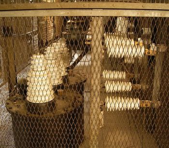
Techniques for the mitigation of noise external to the instrument vary according to the nature of the noise. Electrical noise generated within nearby equipment propagates through air. A way of blocking it is via the Faraday cage.
Less elaborate techniques may be less expensive. Often, interference can be reduced to an acceptable level by boosting the signal strength, raising the signal-to-noise ratio. Alternately, rearranging the equipment layout can reduce interference from radio or TV transmission lines and antennas, subway and high-voltage lines, motors, elevators, triac lamp dimmers, heat controllers, large transformers and welders. AC powerline noise can be effectively eliminated by means of RF line filters and transient suppressors. Shielded lines, installed in grounded conduit, are less noisy. Low-level, high-impedance signal lines must be shielded, as well as all sensitive instrument cabinets.
Signals within an instrument enclosure often get jumbled due to capacitive coupling. These lines, either in the initial design or in existing equipment, can be spaced farther apart and where possible arranged so the runs are not parallel. Twisted conductors in conjunction with differential signaling are far less vulnerable to interference caused by unintended capacitive or inductive coupling. It is helpful also to move the wires closer to grounded metal, which tends to absorb the noisy radiation.
Sensitive circuitry in close proximity to a large power transformer is likely to pick up substantial 60-Hz hum. Here again, relocating the sensitive wires and use of twisted conductors are effective remedies.


Leave a Reply
You must be logged in to post a comment.