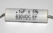
Usually a capacitor’s value in microfarads or picofarads is printed on its housing or there is a color code there. But sometimes we need to measure the amount of capacitance. For example, an electrolytic capacitor may lose capacitance over time (and exhibit more series resistance as well). In critical applications, this effect can be catastrophic. Electrolytic capacitors are likely to lose capacitance while sitting idle on a shelf as opposed to operating in a circuit. As a matter of fact, these capacitors can sometimes be rejuvenated by subjecting them to a regimen of a gradually rising dc voltage.
 And there are other times when a capacitance is unknown and we need to measure it. An example is when we would like to know the capacitance of an overall electrical environment as within a piece of electrical equipment or at its input or output terminals. Or we might want to measure the input capacitance of an oscilloscope probe just to find out what is going on.
High-end multimeters can measure capacitance, but the readings cannot always be considered definitive. I once measured a large number of new non-electrolytic capacitors and found an average deviation from the marked value of over 10%.
In some applications, the exact amount of capacitance is not critical. For example, a large variation is acceptable in a motor starting circuit. In contrast, a resonant circuit requires the exact value for precise tuning.
An oscilloscope can be used to measure a time constant as a means of finding the actual capacitance of a device or the amount of distributed capacitance in an electronic system. While a scope won’t provide a direct readout of capacitance, the capacitance may be calculated because it relates directly to the time constant of an RC circuit when a dc voltage is applied.
The time constant of an electronic circuit that contains resistive and capacitive elements is represented by the Greek letter tau (τ). This time constant in seconds is equal to the circuit resistance in ohms times the circuit capacitance in farads, τ = RC. Tau is the time required to charge a capacitor that is in series with a resistor to a level of 63.2% of the initial value, typically 0 V.
 A digital storage oscilloscope can readily display voltage plotted against time in a capacitor charging or discharging through a resistor. Then the time constant of the circuit can be calculated and, from that, the value of the capacitor can be found.
If you apply a dc voltage to a capacitor in series with a resistor, its charge rises, at first rapidly, then more slowly as it approaches the supply voltage. Plotting voltage against time, the curve seen on an oscilloscope display is known as exponential rise. Conversely, the discharge of a capacitor in series with a resistor is known as exponential decay.
Theoretically, the voltage across a capacitor never becomes equal to the full battery voltage because the rate of change declines as it approaches that level. The time constant by definition is the time in seconds required for the charge as measured at the capacitor terminals to equal 63.2% of the applied voltage.

This phenomenon can be demonstrated easily by connecting a digital multimeter in the ohms mode across an electrolytic capacitor. Depending on the polarity of the meter hookup and also whether or not the capacitor is charged, the resistance will start low and rise or start high and drop in a measured fashion, gradually slowing until it appears to stop. Electricians say that the ohmmeter is counting, and this indicates that the device is not defective. The uncharacteristic reading is because the meter’s internal battery is intentionally biasing the capacitor so resistance can be measured. A typical amount is 3 V. Most instrument manufacturers color the probes red for positive and black for negative, but this is not universal and should be verified using a second multimeter.
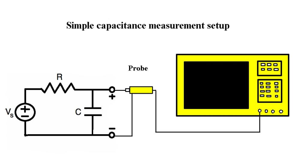
To determine an unknown capacitance using an oscilloscope, a dc power source such as a 9-V battery, a known resistance, a switch and the capacitor are all connected in series. An oscilloscope probe tip and ground lead are connected across the capacitor. Additionally, you need a short wire jumper to shunt across the capacitor.
When the switch is moved to the on position, the scope display graphs the voltage across the capacitor. Because the instrument is in the time-domain mode, amplitude in volts displays on the Y-axis and elapsed time is on the X-axis. The task before us is to find the time constant of the resistor and capacitor that are in series. To do this, determine the final charge on the capacitor, which should be substantially equal to the nominal battery voltage. Then, multiply that amount by 0.632 because the time constant is by definition based on 63.2% of the maximum charge on the capacitor.
Locate that point on the oscilloscope trace, using a horizontal line from the Y-axis. Next, from that point on the charging curve, drop a vertical line down to the X-axis, which must be calibrated in seconds. (A cursor may be used for this purpose.) This provides the time constant of the RC combination, τ. With the time constant known, it is a simple matter to find the unknown capacitance.
As stated earlier,
τ = RC
Transposing,
C = τ/R
Recalling that in the time constant equation C is expressed in farads, the large value for R, which is known, in the denominator yields a reasonable value for the capacitance expressed in microfarads, millionths of a farad. This is the unit more commonly used.

Interesting article re cap measurement on ‘scope.
Having recently bought a second-hand Kukuisu 20 MHz dual-trace CRT scope,
I found that if any capacitor is series connected on signal line from output CH1.output to CH1.X input, the feedback produces a sinewave, with resonant at the cap’s frequency f=1/((2*pi())*C).
So by swapping C (farads) and f (Hertz), capacitance is easily calculated.
By increasing Time/Div resolution to 0.2us and reading 200 cycles across 10 graticules of the display, or 20 cy/div, I could read a maximum frequency of 100MHz before it became too unstable and blurry.
100MHz maximum translates to 4.7nF minimum.
I guess owners of higher resolution ‘scopes could probably measure into the pF range, with careful test-layout.
Regards, Clive.
Electrolytic capacitors normally deviate from their listed value on the label by sometimes 20% or more. Most likely this is why the values od the elwcteolytics you tested were odd by 10%. Your meter is probably just fine but the electrolytics were within their very wide tolerances. Good article though. Very informatice. I got the idea to throw an unknown cap into an RC oscillator with a known resistance and using maths to works out the capacitance. But I realize now thay won’t take ESR into account, whuch would also alter the RC time constant. Thanks for making this. Cheers.
Thanks, it was interesting and useful
I have read an article that stated that if the voltage of accessible surface of device is more than 33v, Touch Current and the levels of capacitive charge or energy shall be measured. I know about touch current but I do not know how to determine capacitive charge…
would you please help me which method is practical?
Hi… This method of using the scope as capacitor meter was published in Wireless word magazine on 1975. I have the original article of Mr. Hennie van Zyl Smit (my partner in Pretoria) dated 1973. Jorge Rodriguez (Pretoria) South Africa