Noise in electronic circuits can be defined in a variety of ways, but it is almost always undesirable. The principal types of noise are thermal noise, shot noise, flicker noise, burst noise and transit time noise.
Thermal noise is always present in an electronic circuit where the temperature of any device or conductor is above 0°K. Where there is any amount of heat, thermal noise results from random motion of charge carriers, a phenomenon always present regardless of the applied voltage or lack of it.
Noise will obscure a signal in proportion to its amplitude. We see this in the noise floor of an auto-ranging oscilloscope where the user is attempting to see a low-amplitude signal. A strong signal, in contrast, will overwhelm the noise floor.
Thermal noise is a form of white noise because its spectral density in terms of power is uniform regardless of frequency. Thermal noise can be mitigated by reducing the temperature of the conductors and devices in which the noise is generated.
Liquid nitrogen is used to cool radio telescope preamplifiers. In astrophotography digital charge-coupled device (CCD) sensors are a source of thermal noise that is cumulative in time exposures. Here also internal cooling is deployed. Amateur astrophotographers drape plastic bags containing ice over their cameras to reduce noise, permitting longer time exposures.
Other types of noise are significant in specific situations. Shot noise arises when charge carriers, crossing a barrier, arrive at the output at discrete intervals. Conventional conductors and non-active devices do not ordinarily exhibit shot noise because the intervals between arrivals are small enough so they are not discerned as discrete events.
Flicker noise is frequency variable, declining at shorter wavelengths, particularly in the presence of direct current. Burst noise is characterized by an intermittent popping or crackling sound when it happens in audio equipment. The intervals are abrupt, with steep transitions. The pulses have fast rise and fall times, but they arise at relatively distant intervals so the overall effect is a low-frequency phenomenon.
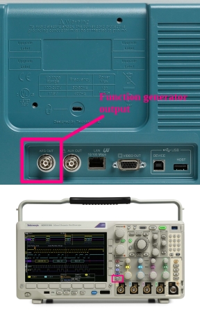
To get an idea of how noise can obscure a signal, we’ll look first at a signal that is not perceptibly so obscured. The Tektronix MDO3104 oscilloscope contains an internal Arbitrary Function Generator (AFG). To see any of its 14 waveforms, run a BNC cable from the AFG jack on the back panel to one of the analog inputs on the front panel. Then, press AFG. By default, Channel One is active and Sine Wave is displayed.
Depending on the most recent signal that has been accessed, it may be necessary to press Autoset to get a good display. Autoset looks at the signal and sets amplitude, time base and triggering levels to optimize the signal as displayed.

Here we see a good signal without significant noise. Small amounts of noise may be present, visible as slight irregularities in the trace. Sources of noise include random motion of electrons in the oscilloscope’s circuitry including flat screen pixels, and possible imperfections in the BNC cable, especially at the terminations. Basically though, we are seeing a very clean signal.
Before adding noise to the signal to see how it can become obscured, we’ll look at a signal that is pure intentionally generated noise.
Press Waveforms and use Multipurpose Knob A to scroll down to Noise. Using the wave Inspector, we can zoom in to take a temporal close-up of the noise signal, simulating what was known in the old analog oscilloscopes as delayed sweep. Notice that when the Wave Inspector knob is turned fully clockwise, a close view of the noise signal is shown in the lower half of the split screen.
Examination of the noise signal reveals its truly random nature. It is akin to what we experience in a radio or TV that is not tuned to a particular station or channel. The automatic gain control goes way up and we hear white noise or see snow, because since there is no received signal, the noise floor becomes prominent.
If the signal has low amplitude, it may not rise sufficiently above the noise floor to be clearly discernable. This is particularly true when using a scope to view a waveform that is obscured by noise.
Returning the instrument to default settings and once more pressing AFG, the sine wave reappears in the display. Now press the soft key that is associated with output settings. In the menu at the right, second item from the top, is Add Noise. The current setting, with no noise added to the sine wave, is 0.00%. Noise can be gradually added to the signal by turning Multipupose Knob A in a clockwise direction.
It is possible to add up to 100% noise to the sine wave. As one would expect, triggering is compromised after a certain amount of noise is added, and this begins to happen at 15%. At this level, a pronounced amount of random electrical energy is apparent in the waveform. At 75%, this becomes very pronounced. Using the Wave Inspector, the character of the noise is evident, and the pure sine wave is largely obscured.
 Another manifestation of noise is apparent when a signal is viewed in the frequency domain. To see this in action, we’ll return the oscilloscope to default settings, again press AFG and this time look at the square wave, which is summoned by pressing the soft key at the bottom that is associated with Waveform. Then turn Multipurpose Knob A in a counter-clockwise direction to access the square wave. Press Menu Off three times so that only the waveform appears in the display. Then press Math, followed by FFT. Again press menu Off. In the frequency domain, the square wave power distribution is shown, becoming less intense as the distance along the frequency spectrum increases from the fundamental.
What is plain to see is that the harmonics, as they diminish in amplitude shown in terms of power on a logarithmic scale, eventually become lost in the noise floor, which as previously mentioned is a thermal phenomenon.
We have examined noise in some of its manifestations. The question now is how can it be mitigated so signals we want to see in the oscilloscope are not obscured. There are several techniques that are useful in this endeavor.
If the noise that accompanies the signal is pre-existing, prior to input into the oscilloscope, it may be possible to partly or totally take it out of the picture by placing a capacitor from probe tip to ground return lead, shunting the high-frequency noise without affecting the lower-frequency signal. Similarly, an inductor can be placed in series with one side of the two-wire circuit. The success of this procedure depends upon fine-tuning the component values.
A highly effective method to control noise that is obscuring a signal is to limit the oscilloscope’s bandwidth. Normally we think of high bandwidth as a desirable feature and we pay a lot for a high-bandwidth instrument. However, when it comes to controlling noise, we can temporarily limit bandwidth and effectively clean up a noisy signal.
To demonstrate, we’ll push AFG, bring up the sine wave, and once again add 50 percent noise. Notice now that the signal is highly compromised. Because noise is cumulative throughout a wide bandwidth, it can be limited by reducing the bandwidth of the instrument. To do so in the Tektronix MDO 3000 series instrument, press the applicable channel button. Then press Bandwidth and cut the bandwidth to 20 MHz. Notice that most of the noise goes away and triggering is stabilized.
Another way to control noise in a signal that is to be observed in an oscilloscope is to use repetitive waveform averaging. The more acquisitions that are averaged, the less noise in the final product. To see how repetitive waveform averaging works, first add noise to a sign wave accessed from AFG. Then press Acquire. The Acquisition Mode menu appears to the right of the display. The bottom choice is Average. Multipurpose Knob a sets the number of waveforms that are averaged. Turn the knob clockwise and watch the noise disappear.

I had no idea there could be so many types of noise due to varieties of reasons. This will be very helpful in troubleshooting as well.