By David Herres
In the field of motion control it’s often necessary to vary the speed of an electric motor and even reverse its direction of rotation. When the application called for this kind of motor control, usual motor technology of choice was that of dc motors until the mid-twentieth century. It was easy to regulate the motor by simply varying the input voltage and polarity. In elevator and similar applications this worked well.
In contrast, it is much tougher to regulate the speed and direction of ac motors. AC motors don’t slow down if they see a reduced input voltage — they simply overheat. The speed of an ac motor is determined by the ac line frequency, not by the amplitude of the input voltage. So reducing the voltage of an ac induction motor that is powering a load is not a good control scheme.
Thus for a long time, it was impractical to operate ac induction motors at anything other than a constant speed. A successful strategy for controlling the speed of ac motors did finally emerge, and today it prevails. Consequently, this development pushed dc motors out of the mainstream and into niche applications.
Worldwide, variable frequency drives (VFD’s) are everywhere. They can vary ac motor direction, torque and/or speed by changing the frequency or duty cycle of the electrical energy the motor sees. The typical VFD for an industrial ac motor typically operates by first rectifying the line voltage (often 440 V three-phase for industrial applications). The resulting dc power travels via the dc bus to an inverter. The inverter generates a pulse-width-modulated waveform. This ac power signal runs the motor, which is usually a three-phase induction motor in industrial settings.
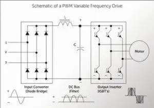 The three-phase rectifier often consists of six diodes, two for each line phase, the two-wire output of which is filtered by two in-line series inductors and two capacitors connected together in series with the pair in parallel across the output. The midpoint between the two capacitors is grounded, a fact that determines how an oscilloscope is to be connected to view the dc voltage, as we shall see.
The inverter, a dc-to-ac converter, receives this pure dc. The inverter generally consists of six insulated-gate bipolar transistors (IGBT’s), which create the pulsed-width-modulated output that powers the motor.
In examining a VFD, the first step is usually to verify the power input (all three legs must be present with no appreciable difference in voltage or current). Next, attention turns to viewing the two-wire dc bus waveform on an oscilloscope.
A point to note is that neither side of the dc bus, negative nor positive, is at ground potential because of the grounded midpoint mentioned earlier. The hooking of a probe ground clip to either side, even before touching the probe tip to anything, will cause a tremendous fault current through the circuit under test, through the probe’s ground lead, back through the oscilloscope and eventually to the service entrance panel. There is a potential for costly damage. To avoid this hazardous situation, there are two possible strategies.
One is to use a hand-held, battery-powered oscilloscope such as the Tektronix THS3024 four-channel, 200 MHz model. It is not line powered and is isolated from ground, so there can be no fault current when connecting either of the probe leads to a wire or terminal that is not at ground potential. This type of instrument is routinely used to display a VFD’s dc bus.
A line-powered bench oscilloscope with a standard probe cannot be connected to a signal source having both sides floating at some potential with respect to ground. But there is a way to use a ground-referenced oscilloscope: Employ a differential probe set. This probe set is designed to make point-to-point measurements where both sides are at a different potential with respect to ground.
The differential probe set amplifies or attenuates the difference between two signals. It then presents that electrical energy to the oscilloscope through one of the analog input channels. It does so without regard for whether or not either side is referenced to ground. This isolates the oscilloscope ground plain from any voltage level that could cause a large fault current.
Tektronix offers differential probes in two versions, low voltage and high voltage. The low-voltage differential probe set is not to be used where the potential between the test points or between either test point and ground exceeds specified limits. Normally the dc bus voltage in a VFD is 1.414 times the ac RMS line voltage. So for a 480-V unit we’re looking at 678 V on the dc bus, requiring the high-voltage differential probe set.
In a future article we’ll look at diagnostic procedures for a typical VFD.

Dear Sir/Ma’am,
Greetings!
I need a clarification with regards to the input power of the VFD, is it possible that a 12V DC Battery Power as an input(of the VFD), and the output is 220 V AC?
Thank you so much.
Sincerely,
JUN,
JUN,
I am not the author of this article and my experience is mainly with uninterruptible power supply’s, which have mostly th same compnents and theory as a VFD. In regards to using the 12v battery as an input power supply for the inverter of the vfd, you will run into some serious obstacles in making that happen. The primary issue being that the system is engineered to run at specific voltages and the DC bus itself will hav been designed to run at a voltage far greater than 12 VDC, msot likely being somwhere between 400-700 VDC. If you were able to make the right connections within the VFD you would need to know exactly what the operating voltage and tolerances are for the DC bus, and then conncect enough batteries is series and maybe parrallel depending on the capacity of said batteries, and then have a way to kep the batteries charged at the specified voltage. I must say that that would be an unlikely scenario and would probably take a lot more work and trouble than the end result would be worth. If you were to attempt to do this you would need to bypass the DC bus all together and go directly to the inverter inputs, which at the same time you would risk destroying the components all together due to the inrush, in my experience almost all UPS’s have a soft start process and will either fail or protect itself from starting if there is not appropriate votlage in the right places, i.e. sense leads, control boards etc
i have a mitsubishi vfd af746 model , its stoping in 36HZ , all setting is right , somone know about this trouble , i have tow error , E.uvt(undervoltage),E.ilf( iput phase loss )
Dear sir
I have vfd yaskawa Model CIMR-H5A4037 can i input source dc insted of 3 phase ac voltage please help. Thanks
Dear JUN,
In VFD, VSI switches between DC bus positive to Negative i.e Vbus +ve and -Ve. So maximum output voltage magnitude will be 12V (neglecting voltage drops on switches and cables), so 220V not possible with 12V supply at DC bus.
Regards
Simplest is to connect the VFD to mains it is rated for and measure the DC bus voltage and you will know what you have to achieve in DC input for your specific VFD.
Theoretically: When AC is rectified to DC it becomes 1.41 times higher.
110×1.41=155v
240×1.41=340v
400×1.41=560v
The VFD is likely to have one of those DC bus voltages depending on model.
A 3-phase 400v VFD may start to operate already at 200v i have seen on youtube but of course not output the full voltage to the motor.
I have not tried this but enough solar panels in series to get the voltage and duplicated in paralell to reach the wattage you need would possibly do it….
The voltage stated on a solar powered VFD is it the MPPT voltage if th ef panels or the open circuit voltage of the panels.
In regards to GOMERCINDO D. POSTANES, JR. s question you need to know the DC buss voltage then you need a DC to DC converter. This is done often but you may want to expect higher input voltage.
I have a DC DC converter with output of above 1000dcv still it can’t power my vfd. why?