• Skip to primary navigation
  • Skip to main content
  • Skip to primary sidebar
  • Skip to footer
  • Advertise
  • Subscribe

Test & Measurement Tips

Oscilloscopes, electronics engineering industry news, how-to EE articles and electronics resources

  • Oscilloscopes
    • Analog Oscilloscope
    • Digital Oscilloscope
    • Handheld Oscilloscope
    • Mixed-signal Oscilloscope
    • PC-based Oscilloscopes – PCO
  • Design
  • Calibration
  • Meters & Testers
  • Test Equipment
  • Learn
    • eBooks/Tech Tips
    • FAQs
    • EE Training Days
    • Learning Center
    • Tech Toolboxes
    • Webinars & Digital Events
  • Video
    • EE Videos
    • Teardown Videos
  • Resources
    • Design Guide Library
    • Digital Issues
    • Engineering Diversity & Inclusion
    • Leap Awards
    • White Papers
  • Subscribe
You are here: Home / Featured / What are insertion loss and return loss and how can I measure them?

What are insertion loss and return loss and how can I measure them?

March 20, 2023 By Rick Nelson Leave a Comment

These basic RF measurements often uncover system problems in wired and wireless communications.

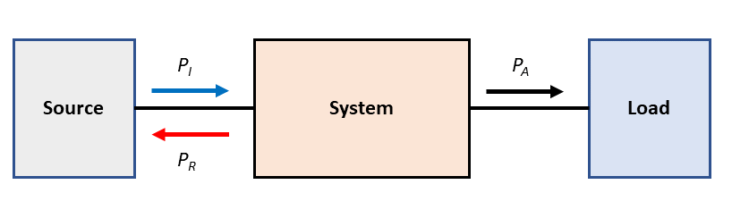
If you observe a signal traveling from a source to a load through a passive system of some sort, you will notice that the signal attenuates by the time it reaches the load, and you will also notice that some of the signal reflects back to the source. Figure 1 shows an incident signal of power PI (blue arrow), reflected signal of power PR (red arrow), and attenuated signal of power PA (black arrow) reaching the load. The attenuation and reflection contribute to insertion loss (IL) and return loss (RL), respectively.

Figure 1. Return loss and insertion loss affect power delivered from a source to a load.

How do we calculate IL and RL?
Let’s start with RL, where we will focus on the source and system (Figure 2), which shows an incident signal of voltage VI and a reflected signal of voltage VR.

Figure 2. Reflections will occur if ZS ≠ ZL.

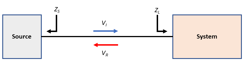
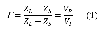
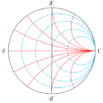
Looking into the source, we see a source impedance ZS, and looking into the load, we see a load impedance ZL. If ZS ≠ ZL, you will have reflections. In recent posts on the Smith chart, I discussed the reflection coefficient:

RL, expressed as a power level in decibels, relates to G  as follows:

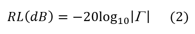
Note there’s a 20 in equation 2 before the log function instead of 10. That’s because G  is a ratio of voltages. For RL, we need a ratio of power levels, which we can get by squaring the voltages or doubling their logarithms—using the latter approach gives us the 20. Table 1 shows some sample values for RL calculated from equation 2.

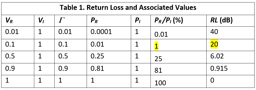
Wait, from your Smith chart posts I know we want to keep G  low, which, from equation 2 and Table 1, implies keeping return loss high. How can high losses be good?
RL indicates loss from the perspective of the reflected signal. As the highlighted entries in Table 1 show, a 20-dB RL indicates that the reflected signal’s power represents just 1% of the incident signal’s power, or in other words, the reflected signal has “lost” 99% of the incident signal’s power. And that’s a good thing, because 99% of the incident signal’s power can continue to the load in Figure 1. Indeed, a 20-dB RL is generally considered good performance.

What about insertion loss?
Insertion loss refers to the amount of signal power lost in a system such as that in Figure 1 due to return loss as well as dielectric, copper, and other losses. For the Figure 1 system, you can calculate insertion loss in decibels as follows:

What instruments do I need to measure IL and RL?
The vector network analyzer (VNA) is the go-to instrument for these measurements. A VNA can measure the scattering parameters s11 and s21, which relate to RL and IL, respectively. Teledyne LeCroy elaborates here on S-parameters and their relationship to IL and RL.

You do have alternatives to the VNA. Tektronix offers an application note describing, among other things, how to use an oscilloscope to measure RL for 1000BASE-T Gigabit Ethernet. To determine IL for the Figure 1 system, you can use a signal generator to generate PI, measure PA with power meter or spectrum analyzer, and calculate IL using equation 3. And finally, time-domain reflectometry (TDR) is useful for evaluating RL. TDR enables distance-to-fault (DTF) measurements. If you have several hundred feet of underground cable that is suddenly exhibiting 0-dB RL, DTF can tell you where to start digging. Anritsu has more here.

You may also like:

  • Smith chart
    What is a Smith chart and why do I need…

  • What is a Smith chart and why do I need…

  • The difference between impedance analyzers and network analyzers

  • The difference between TDR and spread-spectrum TDR

Filed Under: FAQ, Featured, vector network analyzer, vector network analyzers Tagged With: Anritsu Company, Tektronix, teledyne lecroy

Reader Interactions

Leave a Reply Cancel reply

You must be logged in to post a comment.

Primary Sidebar

Featured Contributions

Why engineers need IC ESD and TLP data

Verify, test, and troubleshoot 5G Wi-Fi FWA gateways

How to build and manage a top-notch test team

How to use remote sensing for DC programmable power supplies

The factors of accurate measurements

More Featured Contributions

EE TECH TOOLBOX

“ee
Tech Toolbox: 5G Technology
This Tech Toolbox covers the basics of 5G technology plus a story about how engineers designed and built a prototype DSL router mostly from old cellphone parts. Download this first 5G/wired/wireless communications Tech Toolbox to learn more!

EE TRAINING CENTER

EE Learning Center

EE ENGINEERING TRAINING DAYS

engineering
“test
EXPAND YOUR KNOWLEDGE AND STAY CONNECTED
Get the latest info on technologies, tools and strategies for EE professionals.
“bills

RSS Current EDABoard.com discussions

  • Right Half Plane Zero
  • dc-dc converter in series
  • Single ended measuring ports and balanced antenna
  • Thermal modelling of repetitive power pulse
  • Permittivity and Permealibility in CST

RSS Current Electro-Tech-Online.com Discussions

  • Microinverters and storeage batteries?
  • Fun with AI and swordfish basic
  • FFC connector white
  • Is AI making embedded software developers more productive?
  • Can I make two inputs from one??
Search Millions of Parts from Thousands of Suppliers.

Search Now!
design fast globle

Footer

EE World Online Network

  • 5G Technology World
  • EE World Online
  • Engineers Garage
  • Analog IC Tips
  • Battery Power Tips
  • Connector Tips
  • DesignFast
  • EDA Board Forums
  • Electro Tech Online Forums
  • EV Engineering
  • Microcontroller Tips
  • Power Electronic Tips
  • Sensor Tips

Test & Measurement Tips

  • Subscribe to our newsletter
  • Advertise with us
  • Contact us
  • About us

Copyright © 2025 · WTWH Media LLC and its licensors. All rights reserved.
The material on this site may not be reproduced, distributed, transmitted, cached or otherwise used, except with the prior written permission of WTWH Media.

Privacy Policy