When testing a device in a fixture, you can use transfer scattering parameters (T-parameters) to help remove the fixture’s contribution from your measurement result.
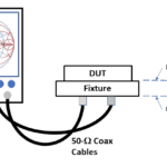
When measuring a device under test, it’s often convenient or necessary to use a fixture — for example, when your instrument has a coaxial connector and your DUT does not. As described in part 1 of this two-part series, after your measurement is complete, you will need to remove the behavior of the fixture from the total measured result to get an accurate measurement of the DUT alone.
You mentioned in part 1 that our two-port DUT requires a fixture with two sections, right?
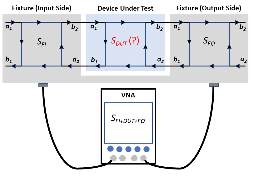
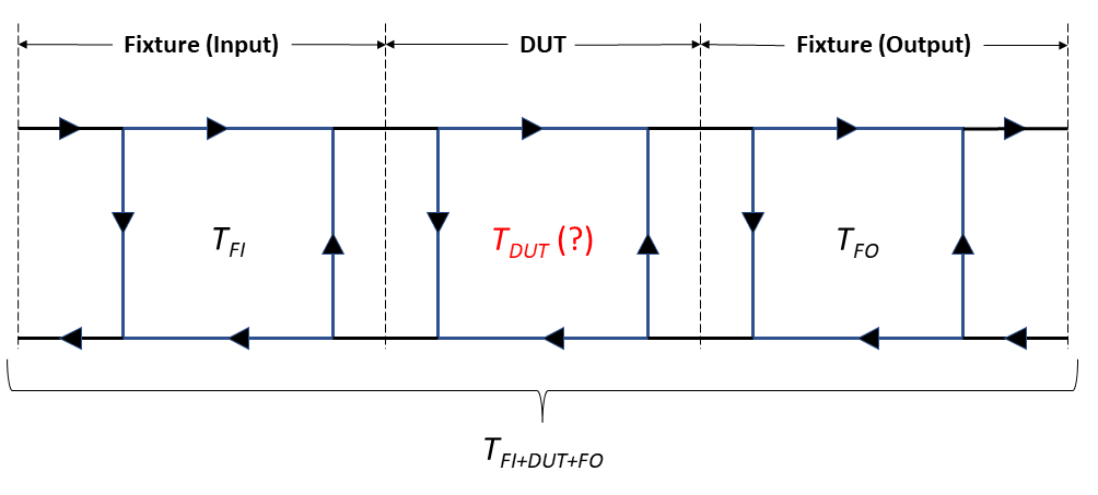
Right. We called them the input and output sections. Figure 1 shows flow diagrams of the two sections of the fixture as well as the DUT along with their S-parameter matrices (SFI and SFO for the fixture input and output sections, respectively, and SDUT for the DUT). We have S-parameter matrices of the fixture sections from models, as described in part 1. Then, use a vector network analyzer (VNA) to measure the S-parameters of the combined fixture and DUT, which we will label SFI+DUT+FO. At this point, the only unknown is SDUT.
OK, so can we just divide SFI+DUT+FO by SFI and SFO to get SDUT?
If the DUT and fixture blocks in Figure 1 were simple gain stages, then we could do that. If the total measured gain is 5 and we know the fixture input and output sections have gains of 0.75 and 0.8, then the DUT gain is 5 divided by 0.75 divided by 0.8 equals 8.33. Unfortunately, S-parameters don’t work that way.
Why not?
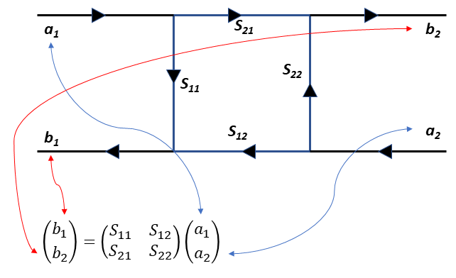
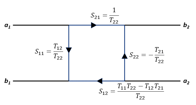
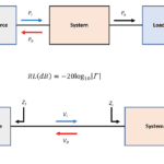
Figure 2, which shows an S-parameter flow diagram and the S-parameter equation, provides an intuitive picture of the problem. The equation expresses the scattered signals (the reflected and transmitted signals) b1 and b2 as functions of the incident signals a1 and a2. Because we have a and b signals at both ends of the network, we don’t have a traditional signal-flow representation of inputs and outputs that would allow us to cascade multiple two-port networks to obtain a larger two-port network — or more to the point for de-embedding, take a cascaded network and separate out the parts representing the fixture.
What’s the solution?
We need a representation that gives us a more traditional input/output signal-flow, with a1 and b1 on one side of the equation and a2 and b2 on the other:
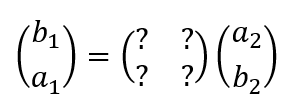 Fortunately, transfer scattering parameters, or T-parameters, can fill in for the question marks. Here’s the equation for a two-port T-parameter matrix:
 You can perform some matrix algebra on the S-parameter and T-parameter equations to find the values of the individual T-parameters in terms of the individual S-parameters, as shown in Figure 3.
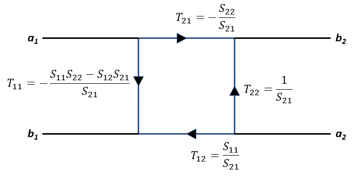
We can now convert SFI+DUT+FO, SFI, and SFO to their T-parameter equivalents, as shown in Figure 4, where TDUT remains unknown.
So how do we get to the de-embedded DUT measurement?
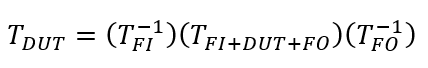
Now we can use division, as you suggested earlier. We can separate out the TDUT matrix from the TFI+DUT+FO matrix by dividing TFI+DUT+FO by SFI, and SFO¬. With matrix algebra, division is best accomplished by multiplying by the inverses of the matrices in the denominator:
 As the final step, we convert TDUT to the desired S-parameter matrix SDUT using the equations in Figure 5, the converse of the equations in Figure 4.
It looks like a lot of matrix algebra, doesn’t it?
Your best bet is to choose a VNA that lets you upload your fixture S-parameter files and then does the calculations for you. Keep in mind that calibration is an inconvenient pre-test process, which may require returning your instrument to the manufacturer or to an independent calibration lab. De-embedding is a post-test process, but many VNAs can do the post-test processing and deliver results in near real time.
Is there an embedding alternative to de-embedding?
Indeed, there is. In some cases, a DUT test involves tuning of some sort. Such a DUT tuned in isolation may require further retuning when it’s integrated into a system with other components. An embedding technique during the initial test — involving S-parameter models of the as-yet unavailable other components — can minimize the need for subsequent retuning at the system level.
Where can I learn more?
Keysight has an application note on de-embedding, with details on converting S-parameters to T-parameters, and vice versa. Rohde & Schwarz has an application note that covers test-fixture characterization and de-embedding for a PCIe connector and other applications. Anritsu comments on how Higher data rates are requiring new de-embedding techniques.

Leave a Reply
You must be logged in to post a comment.