The phrase and concept “orthogonal” is widely used in engineering, but it is also often misunderstood.
The formal definition of orthogonal signals does not necessarily mean that they are unrelated or uncorrelated, although that is how the term is often used in casual “engineering speak.” Formally, two vectors are orthogonal if their dot product is zero, using the standard inner-product (dot product) equation for function spaces:
⟨f,g⟩=∫f(x)g(x) dx
Solving this integral for a single period from t1 to t2 and using f(x) = cos(x) and g(x) = sin(x) yields an inner-product result of zero; thus, sine and cosine are orthogonal. While they are certainly orthogonal functions, they are not the only ones; many other vectors (functions) are also orthogonal.
Orthogonal signals are used extensively in the communications industry, as they allow more information to be conveyed within a frequency channel while minimizing errors. This approach signals begin with simple sine/cosine waveforms referred to as quadrature signals and can be used to send and receive separate information channels on a single frequency with minimal interference between them.
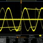
Consider the general situation of two unrelated, independent baseband analog signals amplitude modulating an in-phase (I) signal (cosine) and a quadrature (Q) signal (sine), both of the same frequency. The two modulated signals are then added to create a single signal for the channel, as the time-domain representation shows (Figure 1).
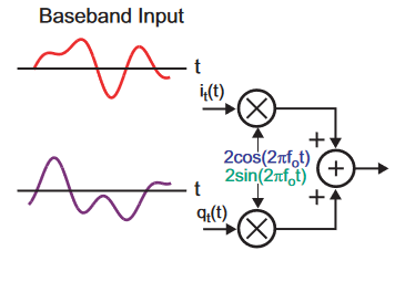
(Note that the I signal is sometimes referred to as the “real” component and the Q signal is referred to as the “imaginary” component – but this does not mean the “I” component doesn’t exist, it just helps with the mathematical analysis if using complex numbers.)
The summed received signal must be demodulated with a local oscillator with the same frequency and phase as the modulating side to recover the original baseband modulating signals. This is called coherent communications and is more challenging than non-coherent communications but offers major benefits in channel capacity and error performance.
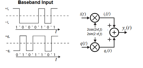
Of course, most communications now use digital signals as data to modulate the carrier – but recall that digital is a subset of analog. In the simplest case, the I and Q signals are modulated with binary (two-state) sequences (Figure 2).
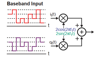
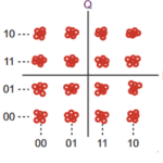
While that provides the highest noise immunity, it does not best use the channel bandwidth and maximum information-carrying capacity, as explained by Shannon’s theory. Among the many other choices are 16-QAM (16-level quadrature amplitude modulation), where the symbols are no longer at just two levels (bits) modulating the I and Q carriers but can take on any one of four levels) values. Thus, the data of each symbol period is no longer a 1 or a 0, but is now a 00, 01, 10, or 11 (Figure 3).
Systems are not limited to 16-QAM (4 combined bits per symbol). Cable modems typically use 64-QAM or 256-QAM, and, for DSL, constellations as large as 32768-QAM (15 bits per symbol) are used routinely. Although this seems like “something for nothing” and a way to increase channel capacity at no cost in performance, that is never the case.
As the number of symbols increases, the separation between them decreases, and noise is more likely to cause an error in the decision-making of the decoding process. At the extreme, think of analog I-Q modulation as having the largest number of symbols per period– an infinite number, in fact – but with zero noise margin between symbols values. There’s always a tradeoff between the channel capacity achieved by the encoding scheme and the noise margin, and thus error rate a higher rate implies.
One highly advanced form of modulation now seeing wide use in applications such as 5G systems is an orthogonal frequency-division multiplexing (OFDM) (Figure 4 and Figure 5). In OFDM, the subcarrier frequencies are selected to ensure that they are orthogonal to each other, so crosstalk between the subchannels is eliminated in theory; in practice, it is greatly minimized) and intercarrier guard bands, which waste valuable spectrum, are not required.
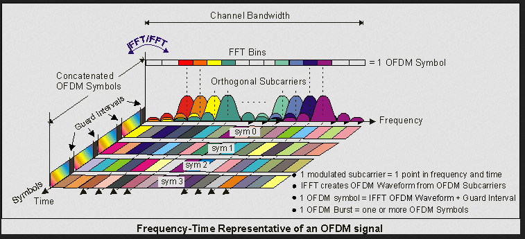
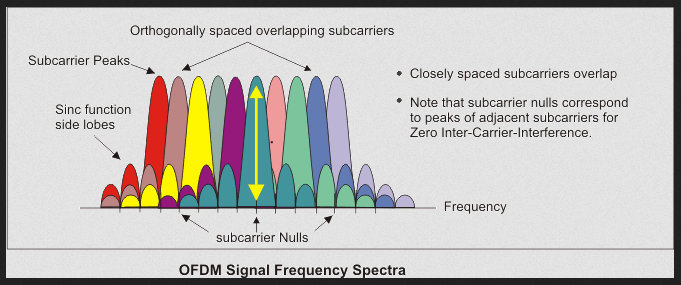
OFDM coding and modulation simplifies the design and implementation of both the transmitter and the receiver for high-capacity narrowband channels. In contrast, in “conventional” non-orthogonal frequency-division multiplexing (FDM), a separate bandpass filter is required for each subchannel. Despite its sophistication and complexity, it is used in various forms in versions of 802.11 Wi-Fi; WiMAX; ITU-T, and DVB-T, (the terrestrial digital TV broadcast system used in most of the world outside North America) as well as 5G. (As OFDM is a complicated topic to explain and explore properly, it will not be discussed further here.)
This more complex, multilevel symbol representation leads to another tool for insight that quadrature modulation offers: the constellation diagram (also called a polar view). This will be discussed in Part 3, along with its complementary perspective, the eye diagram.
EE World Related Content
The basics of 5G’s modulation, OFDM
Is Li-Fi “To Be” or “Not To Be”? Part 2 – Attributes
Reaction wheels ensure satellites maintain the right attitude: Part 1
What does an eye diagram or eye pattern on an oscilloscope mean?
Basics of eye diagrams
Eye and Constellation Diagrams, Pt 2
Eye and Constellation Diagrams, Pt 1
Electric locomotives and catenary power systems – Part 3: power delivery
Generating sine waves from triangle waves
Additional References
Orthogonality
- Physics Classroom, “Forces in Two Dimensions”
- Stack Exchange, “When are two signals orthogonal?”
- Wikipedia, “Orthogonality”
- All About Circuits, “Orthogonal signals”
- Math Reference, “Fourier Transforms, Sines and Cosines are Orthogonal”
- Math Stack Exchange, “What does it mean when two functions are “orthogonal”, why is it important?”
- MIT, “Orthogonal Functions and Fourier Series”
- University of California/Berkeley, “Orthogonal Signaling”
- MIT, “Analog and Digital I/Q Modulation”
- Princeton University, “From AM Radio to Digital I/Q Modulation”
- Tektronix, “What’s Your IQ – About Quadrature Signals”
- NuWaves Engineering, “Application Note AN-005: Understanding Constellation Diagrams and How
They Are Used” - com, “What is a Constellation Diagram?”
- Keysight Technologies, “Concepts of Orthogonal Frequency Division Multiplexing (OFDM) and 802.11 WLAN”
Orthogonal versus uncorrelated: issues
- Stack Exchange, “What is the relationship between orthogonal, correlation and independence?”
- Statistics How To, “What is Orthogonality in Statistics?”
- GitHub, “Orthogonality Does Not Imply Uncorrelated-Ness or Independence”
- Brereton, R. G., Journal of Chemometrics, “Orthogonality, uncorrelatedness, and linear independence of vectors”


Leave a Reply
You must be logged in to post a comment.