The phrase and concept “orthogonal” is widely used in engineering, but it is also often misunderstood.
Just as both the time domain and frequency domain are two legitimate ways of looking at a signal from different perspectives linked by the Fourier transform, the constellation diagram has a time-domain complement called the eye diagram or eye pattern. Like the constellation diagram, it reveals a great deal about the channel condition and signal space and is both qualitative and quantitative. However, unlike the constellation diagram, it is not restricted to quadrature signals, although it is widely used for them, with one eye diagram for the I signal and one for the Q signal.
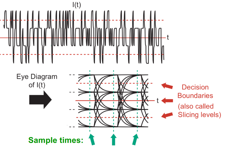
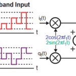
The eye diagram is conceptually simple: it overlays all received and decoded signals starting at the same symbol point in time and shows transitions between symbol states. As more symbols are overlaid, it reveals all possible symbol transition trajectories. It can be used for binary signals as well as multilevel signals, such as the eye pattern for a 16-QAM signal (Figure 1).
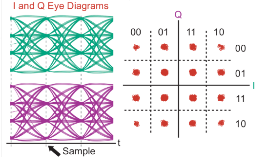
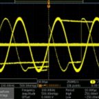
If the channel and signal decoding do not impair or distort the signal, the eye will be fairly wide open (if it were as perfect, the eye would have no fuzziness at all) (Figure 2).
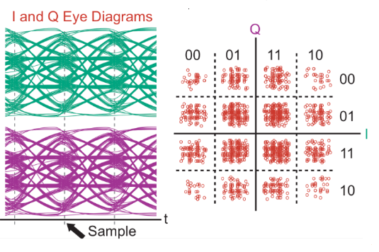
As noise, distortion, and intersymbol interference affect the channel, the eye becomes more closed (Figure 3), another perspective of the constellation diagram’s information.
The eye diagram can be used to understand the channel impairment’s nature qualitatively. Fuzziness around the crossing points indicates timing problems, the closing of the eye reveals noise, skewing of the eye indicates bandwidth limitations and more. Like the constellation diagram, the eye pattern requires only a standard oscilloscope, with its horizontal (time) channel synchronized to the system clock. Some oscilloscopes include “mask”, which are overlaid electronically on the scope screen to show if the eye pattern and this link meets industry-defined standards for performance and bit error rate (BER)
Both the constellation pattern and the eye diagram can be used in real-time to observe the impact of changes in the channel, as well as the results of “fine-tuning” the channel and system when using various adaptive filters or algorithms. Watching the constellation point could expand, shrink, and shift, or the eye to change shape and open/close while making these changes is like watching an MRI or X-ray image in real-time.
Conclusion
Orthogonality is an important topic and design issue in many engineering disciplines. It allows for signals and forces to be resolved into — or employed as — independent components for analysis and construction. Understanding what it means in mathematically rigorous terms is important, as is understanding what it implies in less-stringent scenarios.
EE World Related Content
The basics of 5G’s modulation, OFDM
Is Li-Fi “To Be” or “Not To Be”? Part 2 – Attributes
Reaction wheels ensure satellites maintain the right attitude: Part 1
What does an eye diagram or eye pattern on an oscilloscope mean?
Basics of eye diagrams
Eye and Constellation Diagrams, Pt 2
Eye and Constellation Diagrams, Pt 1
Electric locomotives and catenary power systems – Part 3: power delivery
Generating sine waves from triangle waves
Additional References
Orthogonality
- Physics Classroom, “Forces in Two Dimensions”
- Stack Exchange, “When are two signals orthogonal?”
- Wikipedia, “Orthogonality”
- All About Circuits, “Orthogonal signals”
- Math Reference, “Fourier Transforms, Sines and Cosines are Orthogonal”
- Math Stack Exchange, “What does it mean when two functions are “orthogonal”, why is it important?”
- MIT, “Orthogonal Functions and Fourier Series”
- University of California/Berkeley, “Orthogonal Signaling”
- MIT, “Analog and Digital I/Q Modulation”
- Princeton University, “From AM Radio to Digital I/Q Modulation”
- Tektronix, “What’s Your IQ – About Quadrature Signals”
- NuWaves Engineering, “Application Note AN-005: Understanding Constellation Diagrams and How
They Are Used” - com, “What is a Constellation Diagram?”
- Keysight Technologies, “Concepts of Orthogonal Frequency Division Multiplexing (OFDM) and 802.11 WLAN”
Orthogonal versus uncorrelated: issues
- Stack Exchange, “What is the relationship between orthogonal, correlation and independence?”
- Statistics How To, “What is Orthogonality in Statistics?”
- GitHub, “Orthogonality Does Not Imply Uncorrelated-Ness or Independence”
- Brereton, R. G., Journal of Chemometrics, “Orthogonality, uncorrelatedness, and linear independence of vectors”


Leave a Reply
You must be logged in to post a comment.