The much-awaited next generation of PCIe makes it important to understand bit error-rate measurements.
Hiroshi Goto, Anritsu Co.
PCI Express (PCIe) 6.0 is being developed to meet the high-speed data transmission needs of emerging applications, particularly data centers supporting 5G. It features a doubling of data rates and other enhanced performance specs but at a cost of added complexity for high-speed interconnect designs. Engineers designing such equipment must verify performance via real-time analysis, an approach that saves time and improves repeatability.
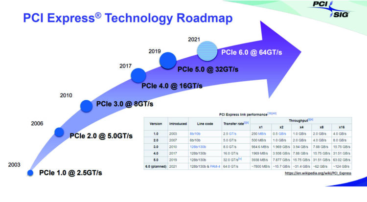
To accommodate faster designs, PCIe 6.0 utilizes 32 Gbaud PAM4 signaling. (Basically, PAM4 is a modulation scheme that combines two bits into a single symbol with four amplitude levels. This effectively doubles a network’s data rate compared to that for 1/0 high-low signaling.) The first five generations of the specification all used Non-Return to Zero, NRZ. (As a quick review, Return to Zero signal transmission of a logic “1” will always begin at zero and end at zero whereas NRZ signal transmission of a logic “1” may or may not begin at zero and end at zero.) PAM4 allows the specification’s channel reach to remain similar to that of the PCIe 5.0 specification. As is the case with all previous PCIe generations, PCIe 6.0 is fully backwards compatible, so NRZ will also be supported.
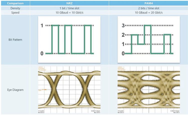
Though the PAM4 scheme doubles the transfer speed, this approach reduces the bandwidth per bit and degrades the waveform, thereby creating a small eye. In other words, the additional signal states of PAM4 signals make them more susceptible to errors than NRZ signals. The underlying frequency is the same as the PCIe 5.0 specification at 32.0 GT/sec NRZ, but there is extra circuitry and logic involved for the PAM4 mode in PCIe 6.0. This is necessary to track three eyes, along with the logic changes needed to operate in what’s called Flow Control Unit (FLIT) mode.
The PCIe 6.0 specification introduces FLIT encoding. FLIT encoding takes place at the logical level to break up data into fixed-size packets. To quickly review, a FLIT is a logical unit of information. A network packet is composed of FLITs. The first FLIT in a packet is the header FLIT and holds information about the packet’s destination address. Subsequent body FLITs contain the actual data payload, and the final tail FLIT performs book keeping to close the connection between the two nodes.
Previous versions the PCIe spec employed no forward error correction. But defining the logical layer in fixed-size packets enables PCIe 6.0 to implement FEC and other error correction methods because such methods require fixed-size packets. Once the link operates in FLIT mode, any speed change to lower data rates will also have to use the same FLIT mode. Once enabled, FLIT mode is followed in the link, regardless of the speed. The improved bandwidth that results from low overhead amortization allows for high bandwidth efficiency, low latency and reduced area.
PAM4 signaling experiences less channel loss because it runs at half the frequency with two bits per unit interval, UI, compared to 1/0 signaling. One byproduct, however is that there is a 10-dB SNR reduction. The three eyes associated with PCIe 6.0 are in the same UI. The result is a reduced eye height and width. Consequently, the bit error rate (BER) is several levels of magnitude higher with PAM4.
For PCIe 6.0, BER is a combination of the First Bit Error Rate (FBER), correlation of errors in a lane, and correlation of errors across lanes. FBER is the probability of the first bit error happening at a receiver in a link. The PSI-SIG conducted extensive studies before determining that the FBER in PCIe 6.0 is 10-6.
PCIe 6.0 uses a unique approach to maintain low latency for these high-speed applications. It integrates lower FBER with low-latency Forward Error Correction (FEC) for initial correction. FEC is an advanced coding technique that transmits the necessary data to correct errors through the PAM4 link. It serves as a key technology to assure transmission quality. It is an essential element in testing because of the reduction in SNR caused by PAM4.
Once FEC takes place, a robust cyclic redundancy check (CRC) detects any errors that remain. The result is a link-level retry mechanism to ensure PCIe 6.0 meets low latency, high-bandwidth, and high-reliability requirements.
The PCI-SIG has established a low latency FEC of below 2 nsec for PCIe 6.0, and that is to be part of the specified overall signal latency of below 10 nsec. FEC is based on a fixed number of symbols. Consequently, it is simple to transition to FLITs, as they are of a fixed size as well.
Evaluating performance
A recommended approach for evaluating performance is to establish an FEC symbol-error threshold. Use of a threshold gives engineers broader control over error conditions that affect patterns during capture by ignoring insignificant events that are normally corrected in the FEC environment.

To set a threshold, a BERT generates a PAM4 signal to the device under test (DUT) receiver input. The DUT determines the logic state of the input signal and loops its decision to the transmitter output. A BERT’s error detector (ED) determines if the DUT’s decision was correct. Here, the BERT’s jitter and noise profiles must comply with standards. And the BERT used to conduct the FEC symbol error measurements should have a high-sensitivity 116-Gbit/sec PAM4 ED.
When conducting the test, it’s important to note that a random error is not as meaningful as one happening in a burst. Also important: Some burst errors cannot be corrected by FEC beyond a certain limit. Post processing must take place beyond that limit to help determine why the DUT might be misreading an incoming symbol. With this approach, engineers can evaluate a device using standard PRBS (pseudo-random binary sequence) patterns while basing error detection capture on events that might be problematic in an FEC environment.
If the input data is captured once the number of FEC symbol errors exceeds the threshold setting, an FEC symbol capture measurement should take place to determine which data stream causes the uncorrectable errors. An uncorrectable burst error is defined as Reed-Solomon (RS) FEC symbol errors that total more than 16 per code word.
A BERT test solution with real-time FEC symbol-capture capability makes for repeatable and high-confidence measurements. Engineers can monitor changes in bit errors and FEC symbol errors with deviations in input amplitude and jitter conditions in as they arise. The input data is captured when the number of FEC symbol errors exceeds the threshold setting, up to 128 burst error events. The causes of FEC-uncorrectable errors can be analyzed from the captured data more efficiently as a result.
The integration of PAM4 technology into PCIe 6.0 has allowed next-generation interconnects to meet the requirements of emerging high-speed applications. A comprehensive test solution that includes real-time FEC analysis capabilities helps engineers verify designs and have greater confidence in product performance.


Leave a Reply
You must be logged in to post a comment.